icon icon icon
KROHNELạc Việt nhà phân phối KROHNE ngành nướcKROHNE water-sector distributor
© KROHNE · MA IFC 300 R07 (10/2024) · MA OPTIFLUX 2000 R09 (03/2026) · TD OPTIFLUX 2000 R14 (03/2026) · TD IFC 300 R10 (10/2024) | Bản HTML Lạc Việt v1.0 · cập nhật 10/10/2026© KROHNE · MA IFC 300 R07 (10/2024) · MA OPTIFLUX 2000 R09 (03/2026) · TD OPTIFLUX 2000 R14 (03/2026) · TD IFC 300 R10 (10/2024) | Lạc Việt HTML edition v1.0 · updated 10/10/2026

Hướng dẫn lắp đặt theo cấu hình · song ngữ · dùng tại hiện trườngConfiguration-specific installation guide · bilingual · for site use

Lắp đặt KROHNE OPTIFLUX 2300 FInstalling the KROHNE OPTIFLUX 2300 F

Cảm biến OPTIFLUX 2000 + converter IFC 300 F (bản rời). Các bước, bảng mô-men, tiếp địa, đấu dây và menu bên dưới được lọc theo đúng cấu hình đơn hàng; mỗi bước ghi trang tài liệu gốc.OPTIFLUX 2000 sensor + IFC 300 F converter (remote). Steps, torque tables, grounding, wiring and menu below are filtered for this order configuration; every step cites the original document page.

Cấu hìnhConfiguration
Tiến độProgress

MA-S p.9–12MA-C p.12–17 Chi tiết trong HandbookDetails in the Handbook ↗

  • Kiểm tra bao bì; nếu hư hỏng hoặc có dấu hiệu va đập, báo đơn vị vận chuyển và văn phòng KROHNE (qua Lạc Việt).Inspect the packaging; report damage or rough handling to the carrier and the local KROHNE office (via Lạc Việt).
  • Đối chiếu packing list với đơn hàng.Check the packing list against the order.
  • Bản rời (F) giao 2 kiện: một kiện converter IFC 300 F, một kiện cảm biến OPTIFLUX 2000.The remote version arrives in two cartons: IFC 300 F converter and OPTIFLUX 2000 sensor.
  • Vật tư và dụng cụ lắp đặt (bulông, gioăng, cáp kích từ…) không nằm trong phạm vi giao hàng.Assembly materials and tools (bolts, gaskets, field current cable…) are not part of the delivery.

MA-S p.9, p.12MA-C p.12, p.37

INFORMATION
Kiểm tra nameplate đúng đơn hàng và đúng điện áp nguồn in trên nameplate trước khi đấu điện.Check that the nameplate matches the order and the supply voltage printed on it before wiring. MA-S p.12MA-C p.12
CAUTION
Cảm biến và converter được cấu hình theo cặp tại nhà máy – hằng số GK/GKL trên hai nameplate phải giống nhau.Sensor and converter are configured as a pair at the factory – GK/GKL on both nameplates must be identical. MA-C p.24
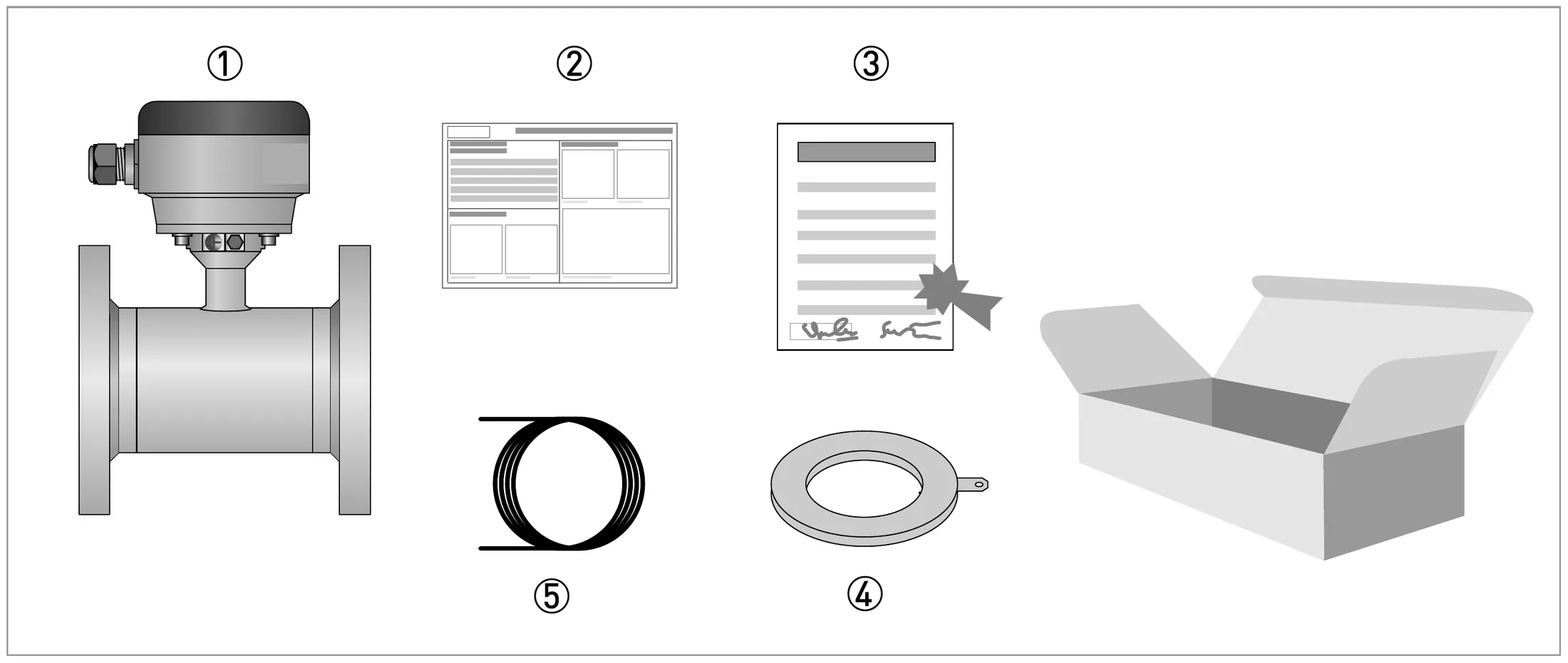
Scope of delivery
  1. 1Đồng hồ theo đơn hàngOrdered flowmeter
  2. 2Tài liệu sản phẩmProduct documentation
  3. 3Biên bản hiệu chuẩn nhà máyFactory calibration report
  4. 4Vòng tiếp địa (tùy chọn)Grounding rings (optional)
  5. 5Cáp tín hiệu (chỉ bản rời)Signal cable (remote versions only)
Phạm vi giao hàngScope of delivery MA-S p.9
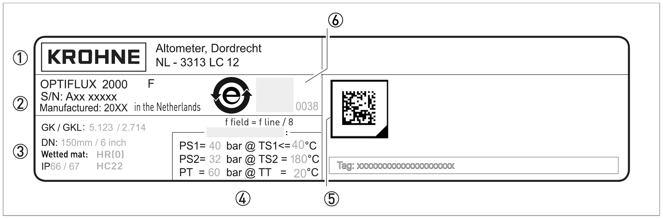
Example of sensor nameplate
  1. 1Tên, địa chỉ nhà sản xuấtName and address of the manufacturer
  2. 2Model, số serial, ngày sản xuấtType designation, serial number and manufacturing date
  3. 3Dữ liệu hiệu chuẩn (GK/GKL, DN, tần số kích từ…)Calibration data (GK/GKL, DN, field frequency…)
  4. 4Dữ liệu PED (áp suất/nhiệt độ)PED data
  5. 5Data Matrix – quét để tải tài liệu, chứng chỉ hiệu chuẩn, file cài đặt nhà máyData matrix – scan to download documents, calibration certificate, factory settings
  6. 6Dấu hợp chuẩn (CE…) và số tổ chức chứng nhận, logo China RoHSConformity marking (e.g. CE) with notified body number(s) and China RoHS logo
Ví dụ nameplate cảm biếnExample of sensor nameplate MA-S p.11
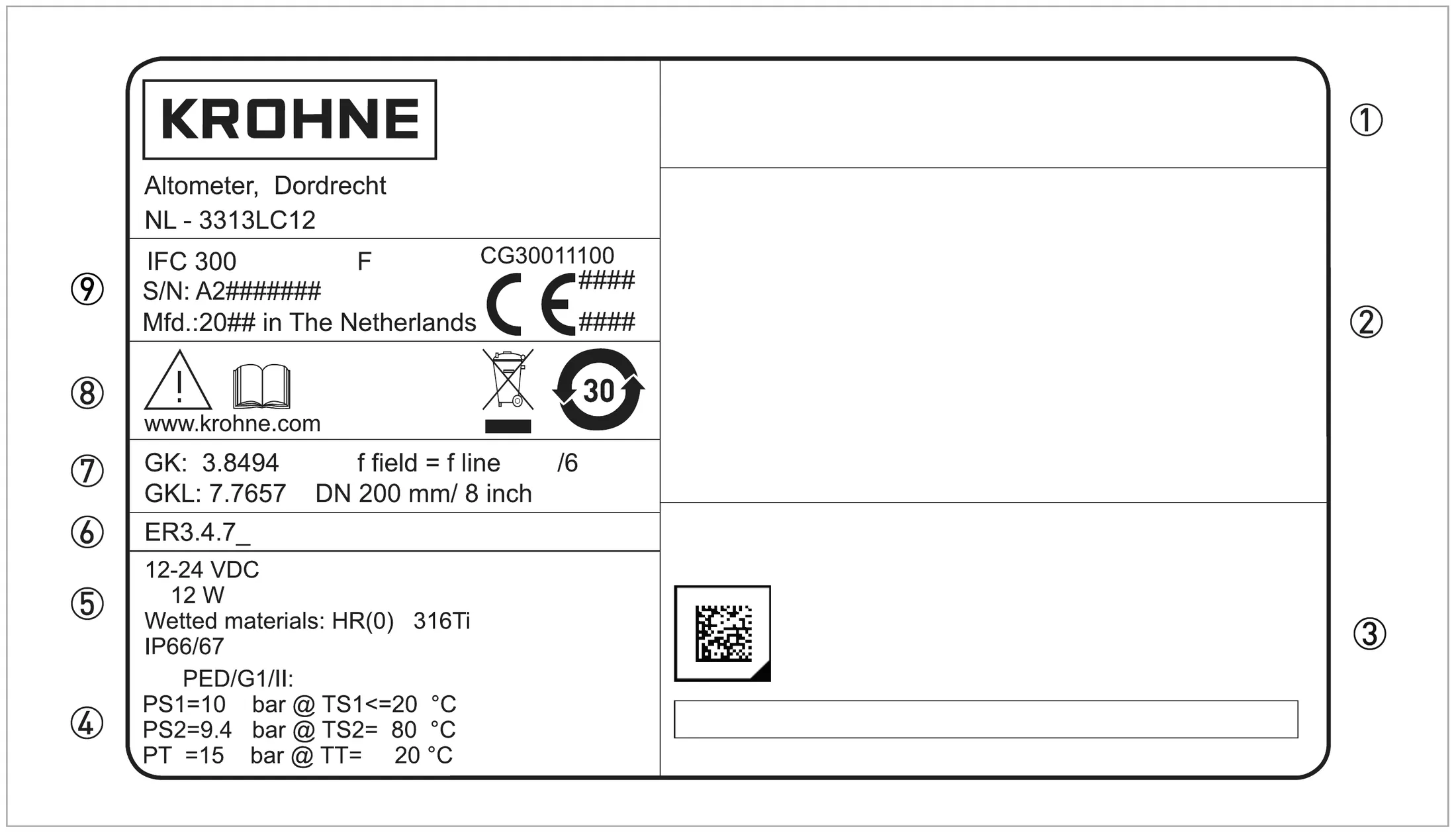
Example of an IFC 300 nameplate
  1. 1Thông tin phê duyệt: Ex, chứng nhận thử kiểu EC, hygienic…Approvals-related information: Ex approval, EC type test certificate, hygienic approvals, etc.
  2. 2Ngưỡng liên quan phê duyệtApprovals-related thresholds
  3. 3Mã Data MatrixData Matrix code
  4. 4Dữ liệu phê duyệt (ngưỡng nhiệt độ, áp suất)Approvals-related data (e.g. temperature and pressure thresholds)
  5. 5Nguồn cấp, cấp bảo vệ, vật liệu tiếp xúc môi chấtData for power supply, ingress protection and materials of wetted parts
  6. 6Phiên bản phần mềm (Electronic Revision)Software revision number (Electronic Revision)
  7. 7GK/GKL (hằng số cảm biến), DN và tần số kích từGK/GKL values (flow sensor constants), size (mm/inch) and field frequency
  8. 8Hướng dẫn an toàn, thải bỏ, China RoHSSafety instructions, disposal and China RoHS marking
  9. 9Tên sản phẩm, serial, ngày/nước sản xuất, mã CG, dấu hợp chuẩnProduct designation, serial number, manufacturing date and country, CG number and conformity mark
Ví dụ nameplate converter IFC 300Example of an IFC 300 nameplate MA-C p.16

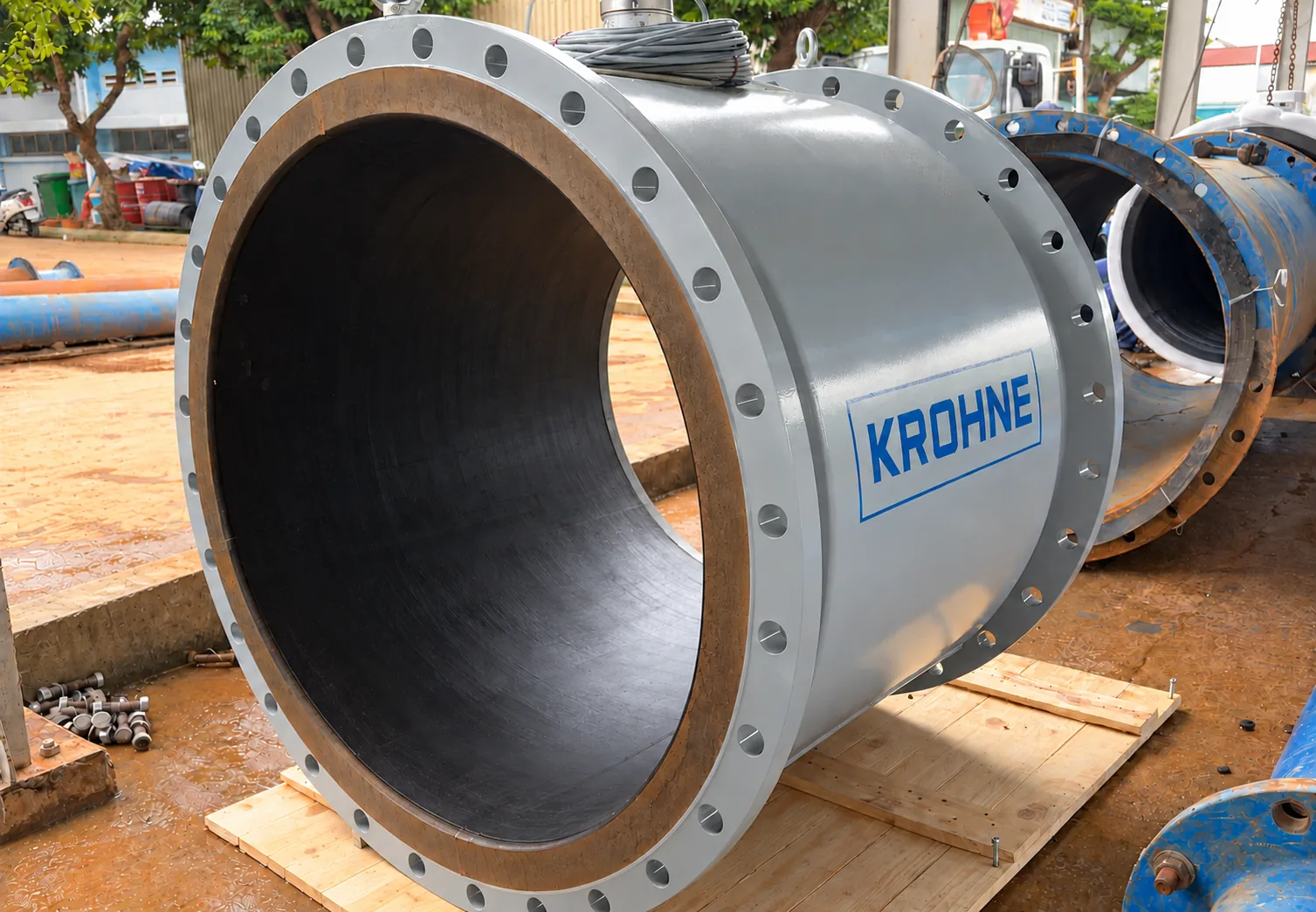
Lạc ViệtDN lớn: chụp ảnh kiện trước khi dỡ; kiểm tra mặt bích, phần lót hard rubber lộ ra ở mặt bích (sứt, nứt), hộp đấu nối và cáp. Giữ nguyên tấm che mặt bích cho đến lúc lắp vào tuyến. Mục này là kinh nghiệm hiện trường, manual không quy định.Large DN: photograph the crate before unloading; check the flanges, the hard-rubber liner at the flange faces (chips, cracks), the connection box and cable. Keep the flange covers on until the meter goes into the line. Field practice – not specified in the manual.

Ảnh thực tế – theo cấu hình đang chọnIn the field – for the selected configuration
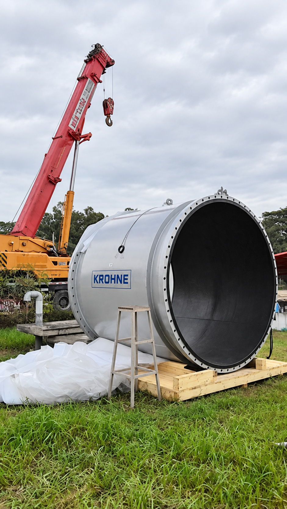
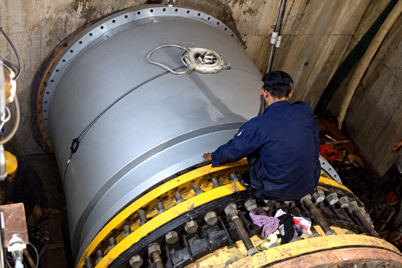
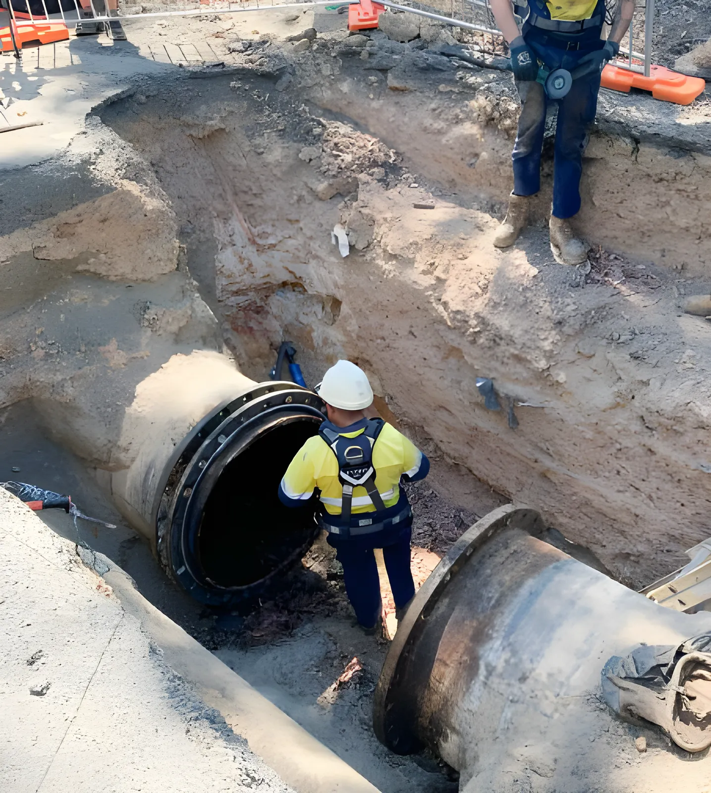
Tiếp nhận đồng hồ DN2400 tại công trường
Tiếp nhận đồng hồ DN2400 tại công trườngReceiving the DN2400 meter on site Ảnh hiện trường thật – Lạc Việt, TP.HCM 2017 · đã chỉnh sáng/làm nétReal site photo – Lạc Việt, HCMC 2017 · brightness/sharpness adjusted
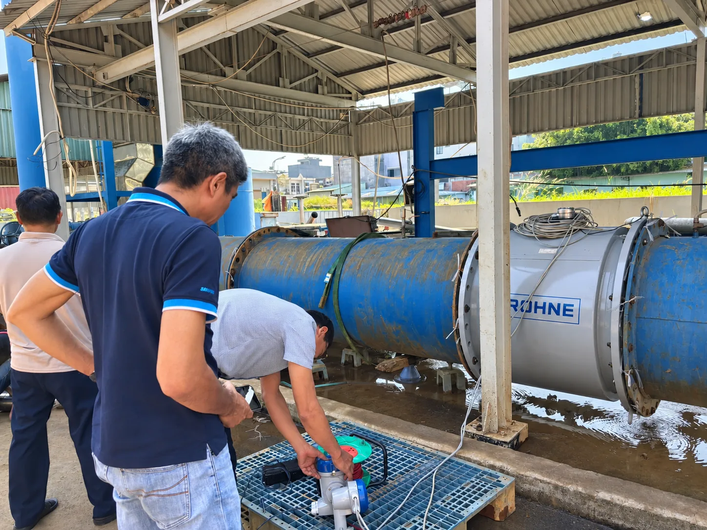
Tiếp nhận DN1000 tại trung tâm kiểm định
Tiếp nhận DN1000 tại trung tâm kiểm địnhDN1000 received at the verification centre Ảnh thực tế – Lạc Việt · DN1000 · kiểm định tại Trung tâm đo lường TP.HCM · 2025 · chỉnh sửa nhẹ (retouch), không thay đổi thiết bịReal photo – Lạc Việt · DN1000 · verification at the HCMC metrology centre · 2025 · lightly retouched, equipment unchanged

Ảnh thực tế – theo cấu hình đang chọnIn the field – for the selected configuration
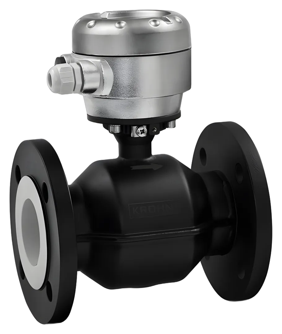
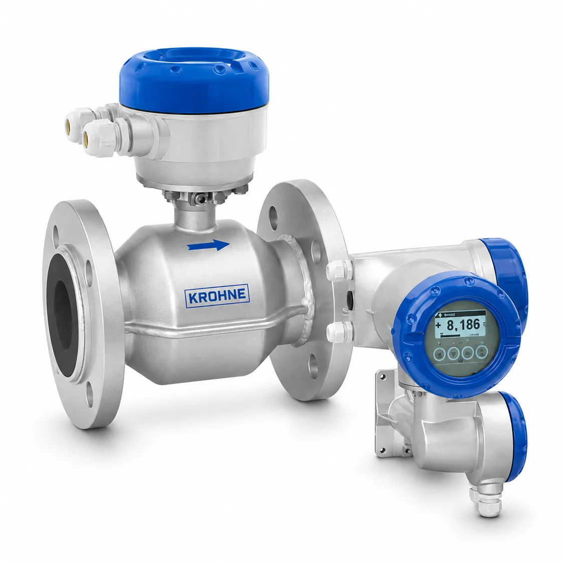
OPTIFLUX 2300 F – cảm biến OPTIFLUX 2000 + converter IFC 300 F (bản rời)
OPTIFLUX 2300 F – cảm biến OPTIFLUX 2000 + converter IFC 300 F (bản rời)OPTIFLUX 2300 F – OPTIFLUX 2000 sensor + IFC 300 F converter (remote) © KROHNE

MA-S p.12 Chi tiết trong HandbookDetails in the Handbook ↗

  • Nơi khô, không bụi.Dry, dust-free location.
  • Tránh nắng trực tiếp kéo dài.Avoid lasting direct exposure to the sun.
  • Giữ trong bao bì gốc.Keep in the original packaging.
  • Nhiệt độ lưu kho: −50…+70 °C.Storage temperature: -50...+70°C / -58...+158°F.

MA-S p.12TD-S p.10

Lạc ViệtKê kiện trên đà/pallet cao khỏi nền, che bạt nhưng vẫn thoáng; không đặt cảm biến tì lên mặt bích có lót; kiện converter IFC 300 cất trong kho có mái. Không tháo bao bì cho đến khi chuẩn bị lắp.Keep crates on timber/pallets off the ground, tarpaulin-covered but ventilated; never rest the sensor on a lined flange face; store the IFC 300 carton indoors. Do not unpack until installation.

MA-S p.12, p.47, p.50 Chi tiết trong HandbookDetails in the Handbook ↗

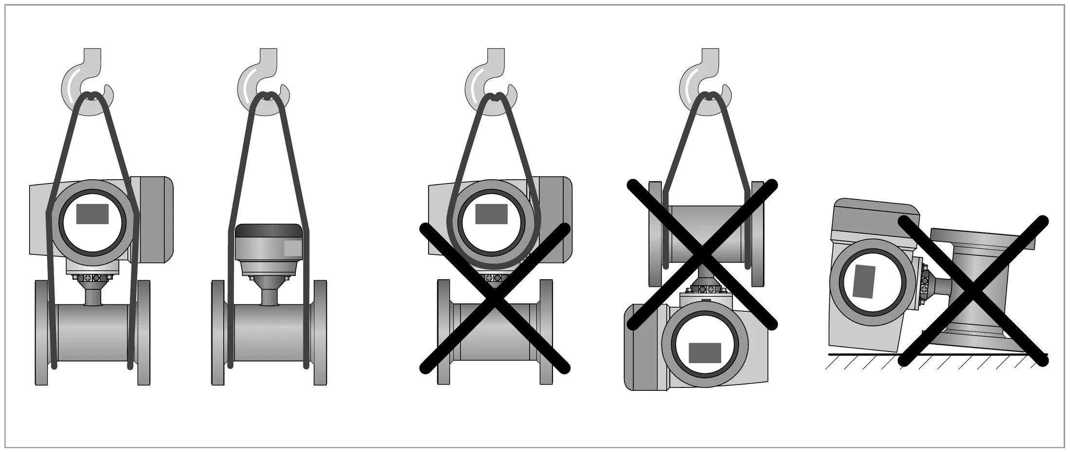
Lifting: straps around both process connections; never by the converter housing, no chains
  1. ✓1Nâng bằng dây đai quấn quanh cả hai đầu kết nốiLift with straps wrapped around both process connections
  2. ✓2Nâng bằng dây đai quấn quanh cả hai đầu kết nốiLift with straps wrapped around both process connections
  3. ✕1Không nâng thiết bị bằng vỏ converterDo not lift the device by the signal converter housing
  4. ✕2Cách không đúng – xem Hình 3-1Incorrect – see Figure 3-1
  5. ✕3Cách không đúng – xem Hình 3-1Incorrect – see Figure 3-1
Cách nâng: dùng dây đai quấn quanh cả hai mặt bích; không nâng bằng vỏ converter, không dùng xíchLifting: straps around both process connections; never by the converter housing, no chains MA-S p.12
  • Thiết bị mặt bích: dùng dây đai cẩu, quấn quanh cả hai đầu kết nối (mặt bích).Flange devices: use lifting straps wrapped around both process connections.
  • Không dùng xích nâng.Do not use lifting chains.
  • Không nâng bằng vỏ converter.Do not lift the device by the signal converter housing.

MA-S p.12

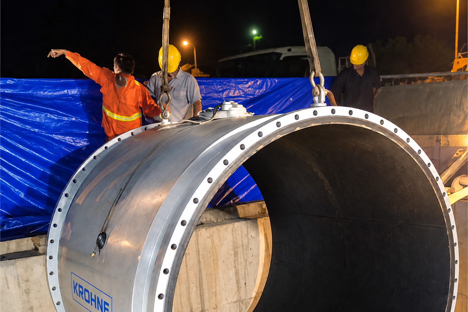
Lạc ViệtBản F: cũng không nâng/kéo bằng hộp đấu nối hay cáp. Chọn cẩu, dây đai có tải định mức lớn hơn khối lượng thiết bị theo quy định an toàn nâng hạ của công trường; dùng thanh gánh để dây không ép vào hộp đấu nối; không luồn dây hay càng nâng qua lòng ống (bảo vệ lớp lót).F version: never lift or pull by the connection box or cable either. Choose a crane and straps rated above the device weight per the site lifting rules; use a spreader bar so straps do not press on the connection box; never pass straps or forks through the bore (liner protection).

Ảnh thực tế – theo cấu hình đang chọnIn the field – for the selected configuration
Cẩu hạ đồng hồ DN2400 (thi công ban đêm)
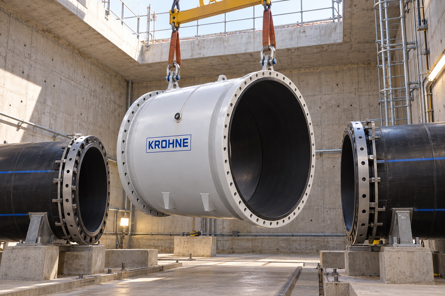
Cẩu hạ đồng hồ DN2400 (thi công ban đêm)Lifting the DN2400 meter (night work) Ảnh hiện trường thật – Lạc Việt, TP.HCM 2017 · đã chỉnh sáng/làm nétReal site photo – Lạc Việt, HCMC 2017 · brightness/sharpness adjusted
Ảnh minh họa: Cẩu hạ đồng hồ điện từ DN lớn vào buồng ngầmẢnh minh họaIllustration
Cẩu hạ đồng hồ điện từ DN lớn vào buồng ngầmLowering a large-DN electromagnetic flowmeter into an underground chamber Ảnh minh họa (dựng hình) – không phải ảnh công trìnhIllustration (staged image) – not a project photo

Ảnh thực tế – theo cấu hình đang chọnIn the field – for the selected configuration

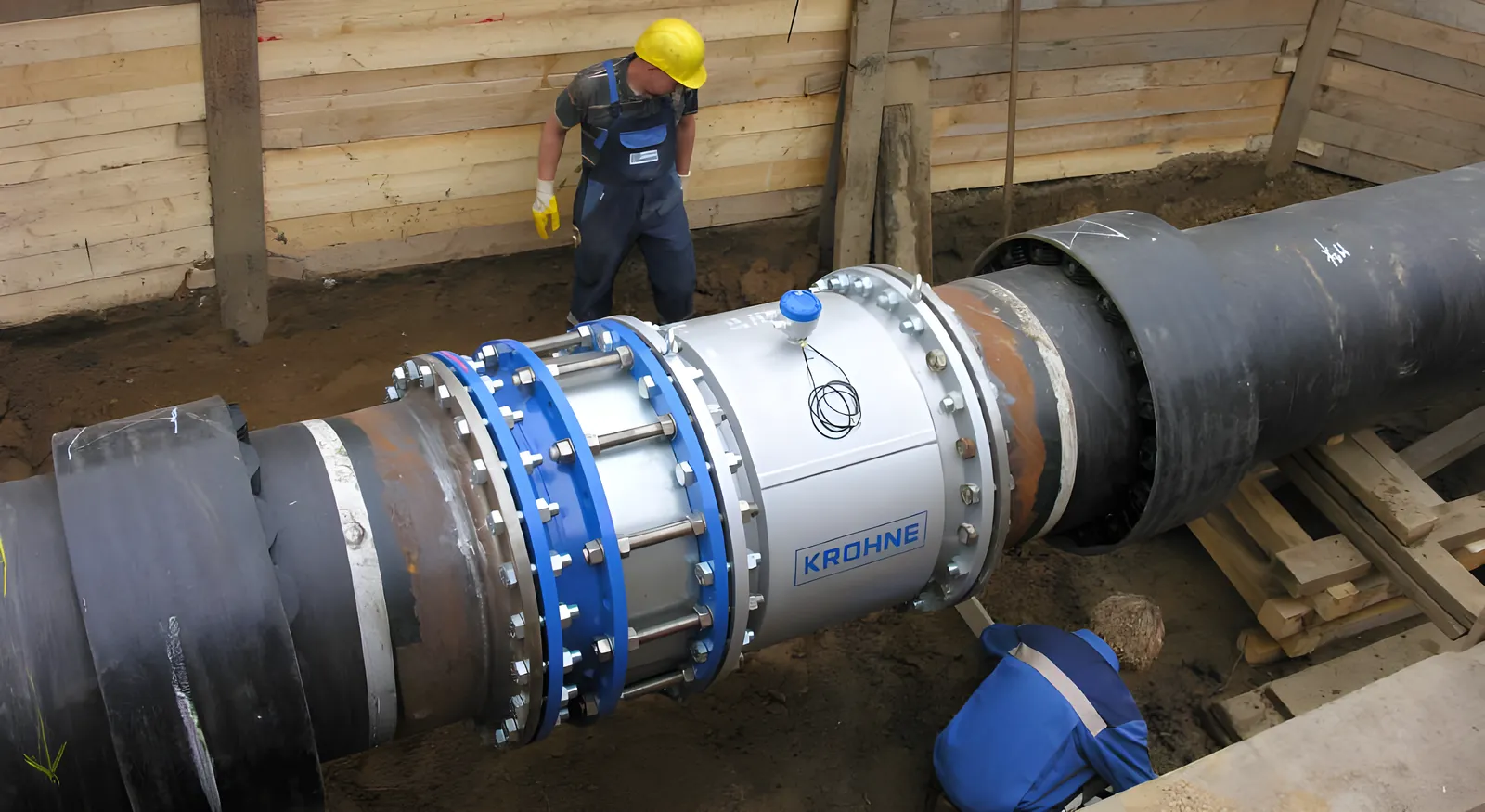
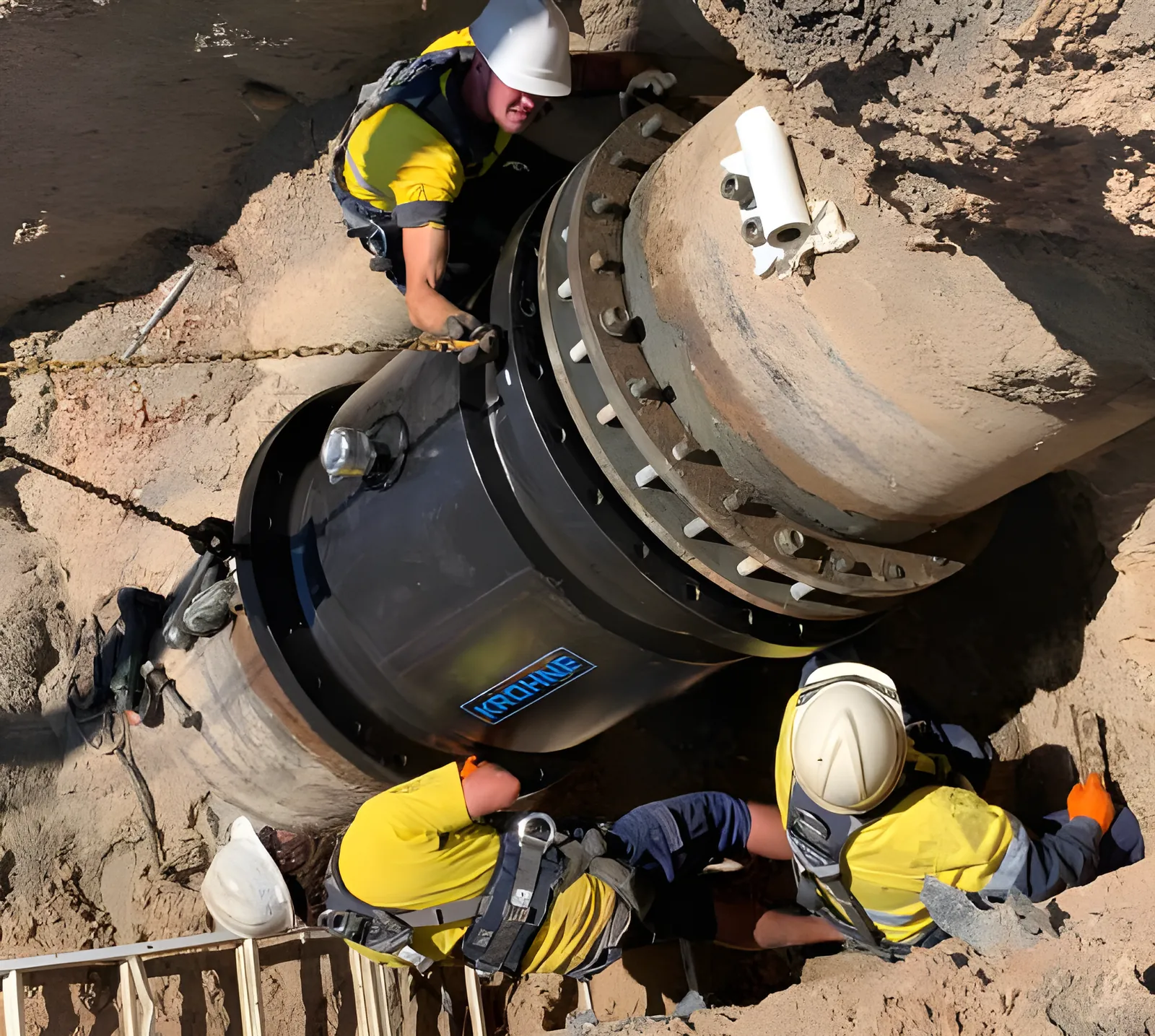
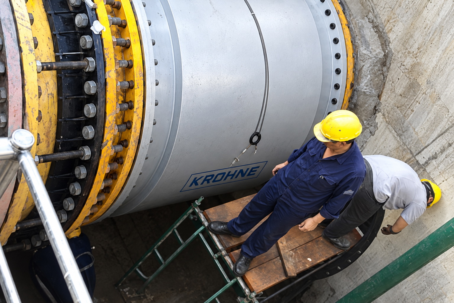
Lắp OPTIFLUX 2300 W DN900 trong hố đào
Lắp OPTIFLUX 2300 W DN900 trong hố đàoInstalling OPTIFLUX 2300 W DN900 in a trench © KROHNE · làm nét bằng AI, không thêm bớt chi tiếtAI-sharpened, no details added Application p.1–2

TD-S p.11–12MA-S p.13–20 Chi tiết trong HandbookDetails in the Handbook ↗
CAUTION
Cảm biến phải luôn đầy nước; tránh để bị rút cạn hoặc chỉ đầy một phần.The flow sensor must always be fully filled; avoid draining or partial filling. TD-S p.12MA-S p.15
Đoạn thẳng & khoảng cách theo tài liệuStraight runs & distances per documents TD-S p.12MA-S p.13–19
Tình huốngSituationYêu cầuRequirementNguồnSource
Đoạn thẳng trước (inlet)Inlet run≥ 5 DNTD-S p.12
Đoạn thẳng sau (outlet)Outlet run≥ 2 DNTD-S p.12
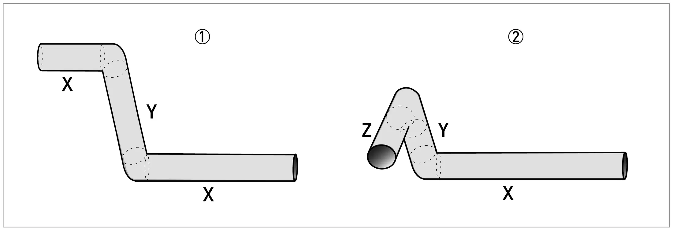
Sau co 2 chiều (X/Y)After 2-D bends (X/Y)≥ 5 DNMA-S p.14
Sau co 3 chiều (X/Y/Z)After 3-D bends (X/Y/Z)≥ 10 DNMA-S p.14
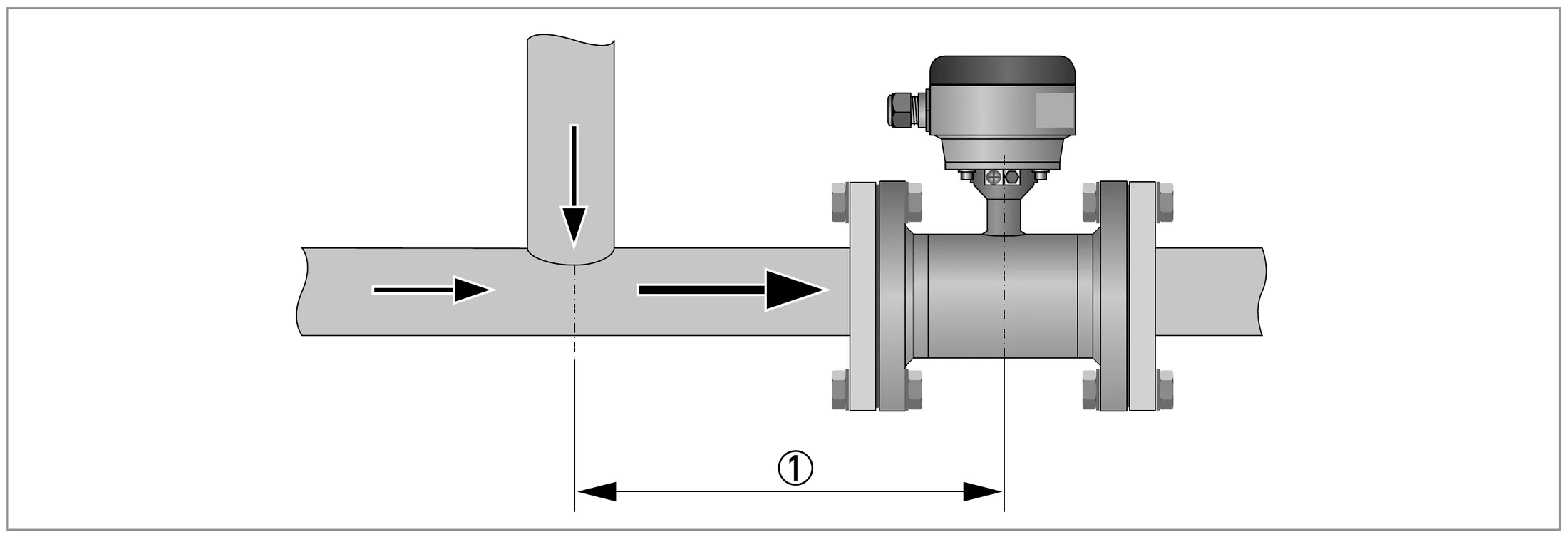
Sau ngã ba TAfter a T-section≥ 10 DNMA-S p.16
Giữa 2 đồng hồ điện từBetween two EM flowmeters≥ 5 DNMA-S p.13
Xả khí / chân khôngAir venting / vacuum≥ 5 mMA-S p.18
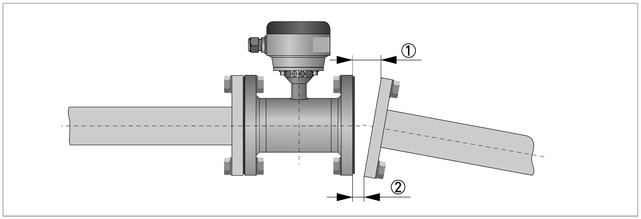
Lệch mặt bích Lmax − LminFlange deviation Lmax − Lmin≤ 0.5 mmMA-S p.19
INFORMATION
DN này nằm ngoài dải chứng nhận OIML R49 / MID MI-001 (đến DN1800) → không áp dụng lắp 0D/0D theo chứng nhận; lắp theo ≥ 5 DN / ≥ 2 DN.This DN is outside the OIML R49 / MID MI-001 range (up to DN1800) → the certified 0D/0D installation does not apply; use ≥ 5 DN / ≥ 2 DN. TD-S p.9
WARNING
Đơn hàng ghi custody transfer OIML R49 (NMi), trong khi TD chỉ liệt kê OIML R49 Class 1 cho DN50…1800. Kiểm tra certificate/biên bản kiểm định áp dụng cho đúng DN này trước khi nghiệm thu; khi chưa xác nhận, lắp theo ≥ 5 DN / ≥ 2 DN.The order states custody transfer OIML R49 (NMi), while the TD only lists OIML R49 Class 1 for DN50...1800. Check the certificate/verification record that applies to this DN before acceptance; until confirmed, install with ≥ 5 DN / ≥ 2 DN. TD-S p.9Spec đơn hàng DN2400
INFORMATION
Lắp 0D/0D chỉ áp dụng trong phạm vi chứng nhận OIML R49 / MID MI-001 với IFC 300 và cấu hình/order code phù hợp. Mặc định lắp ≥ 5 DN / ≥ 2 DN.0D/0D only applies within the OIML R49 / MID MI-001 certification with IFC 300 and a matching configuration/order code. Default: ≥ 5 DN / ≥ 2 DN. TD-S p.9MA-S p.14
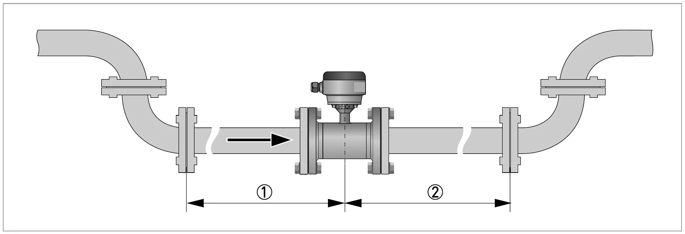
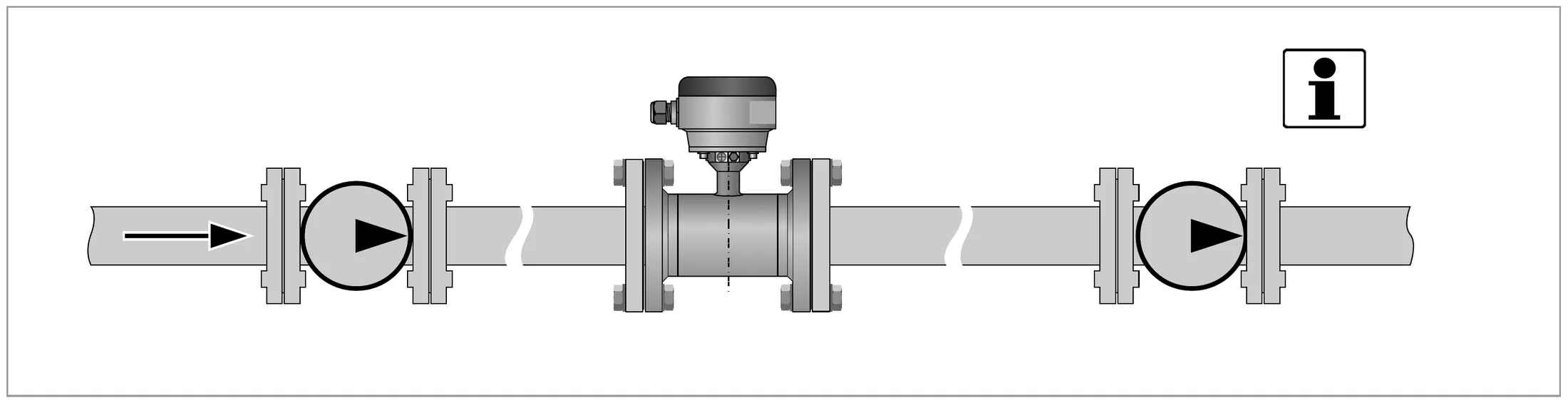
Recommended inlet/outlet: ① see "bends in 2 or 3 dimensions"; ② ≥ 2 DN
  1. ①Xem mục "Co 2 hoặc 3 chiều"Refer to "Bends in 2 or 3 dimensions"
  2. ②≥ 2 DN≥ 2 DN
Đoạn thẳng khuyến nghị: ① xem mục co 2/3 chiều; ② ≥ 2 DNRecommended inlet/outlet: ① see "bends in 2 or 3 dimensions"; ② ≥ 2 DN MA-S p.14
Bends in 2 dimensions (X/Y): inlet ≥ 5 DN; in 3 dimensions (X/Y/Z): ≥ 10 DN
  1. ①Co 2 chiều = X/Y2 dimensions = X/Y
  2. ②Co 3 chiều = X/Y/Z3 dimensions = X/Y/Z
Co 2 chiều (X/Y): đoạn trước ≥ 5 DN; co 3 chiều (X/Y/Z): ≥ 10 DNBends in 2 dimensions (X/Y): inlet ≥ 5 DN; in 3 dimensions (X/Y/Z): ≥ 10 DN MA-S p.14
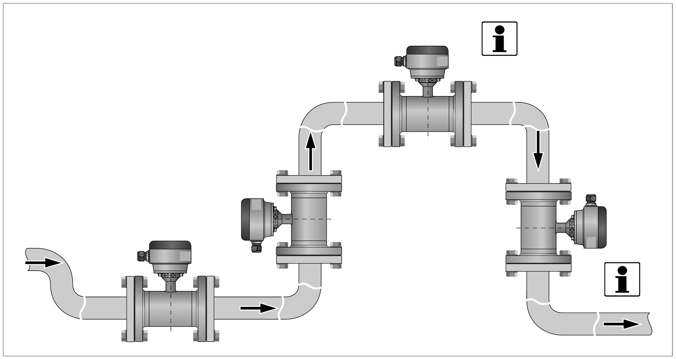
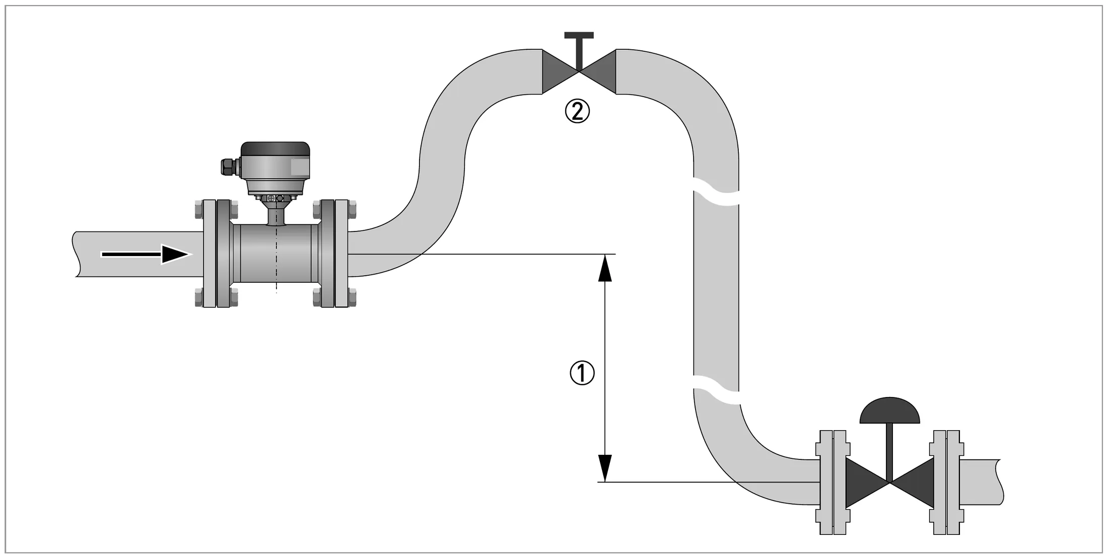
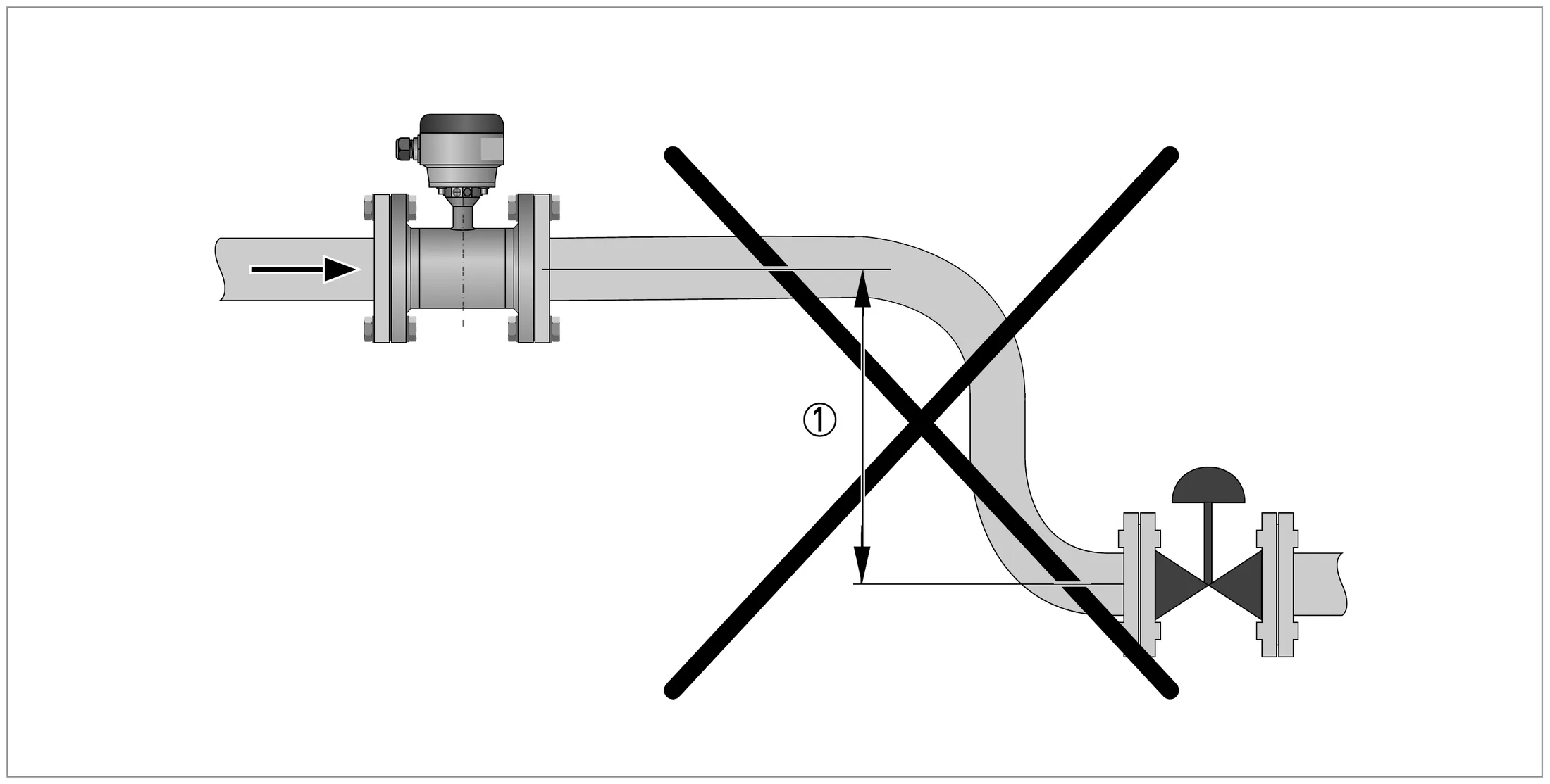
Installation in bending pipes (90°)
  1. ✓1Khuyến nghị: đoạn ống thấpRecommended: lowered pipe section
  2. ✓2Khuyến nghị: đoạn ống đi lênRecommended: ascending pipe section
  3. ✕Điểm cao nhất: tăng rủi ro lỗi do bọt khí/khíHighest point: higher risk of malfunction from air/gas bubbles
Lắp ở đoạn ống co 90°Installation in bending pipes (90°) MA-S p.15
  • Vị trí khuyến nghị: đoạn ống thấp hoặc đoạn đi lên. Điểm cao nhất dễ đọng khí → đo sai.Recommended: a lowered or ascending section. The highest point risks malfunction from air/gas bubbles.
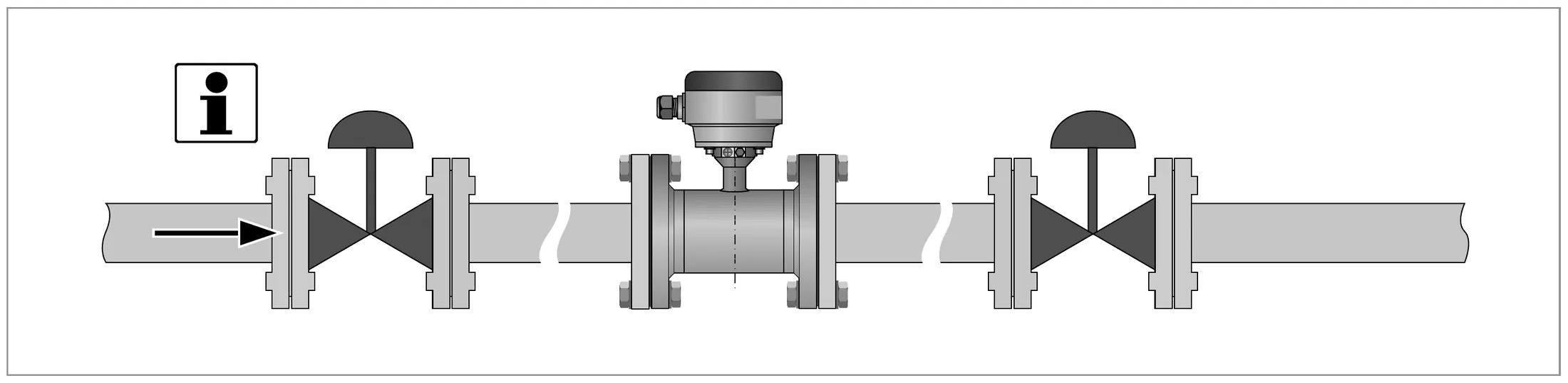
  • Nên lắp trước van điều khiển; sau van chỉ khi không có xâm thực.Install upstream of a control valve; downstream only without cavitation.
  • Nên lắp sau bơm, ở vị trí nhiễu dòng đã ổn định.Install downstream of a pump where its disturbances are resolved.

MA-S p.15–17

Behind a T-section: ① ≥ 10 DN
  1. ①≥ 10 DN≥ 10 DN
Sau ngã ba T: ① ≥ 10 DNBehind a T-section: ① ≥ 10 DN MA-S p.16
In front of a control valve
  1. ✓Khuyến nghị: lắp phía trước van điều khiểnRecommended: upstream of a control valve
Lắp trước van điều khiểnIn front of a control valve MA-S p.17
Behind a pump
  1. ✓Khuyến nghị: lắp phía sau bơm, nơi dòng đã ổn địnhRecommended: downstream of a pump, where flow disturbances are resolved
Lắp sau bơmBehind a pump MA-S p.17
Air venting: ① ≥ 5 m / 17 ft; ② air ventilation point
  1. ①≥ 5 m≥ 5 m / 17 ft
  2. ②Điểm xả khíAir ventilation point
Xả khí: ① ≥ 5 m; ② điểm xả khíAir venting: ① ≥ 5 m / 17 ft; ② air ventilation point MA-S p.18
Vacuum: ① ≥ 5 m / 17 ft
  1. ①≥ 5 m≥ 5 m / 17 ft
  2. ✕Cách không đúng – xem Hình 3-13Incorrect – see Figure 3-13
Chân không: ① ≥ 5 mVacuum: ① ≥ 5 m / 17 ft MA-S p.18

Giới hạn lưu chất với IFC 300: khí ≤ 5 % thể tích; chất rắn ≤ 70 % thể tích. Dải vận tốc đo −12…+12 m/s.Fluid limits with IFC 300: gas ≤ 5 % by volume; solids ≤ 70 % by volume. Measuring range -12...+12 m/s. TD-S p.10–11

Hố đo ngập nước & chôn ngầmFlooded pit & buried installation

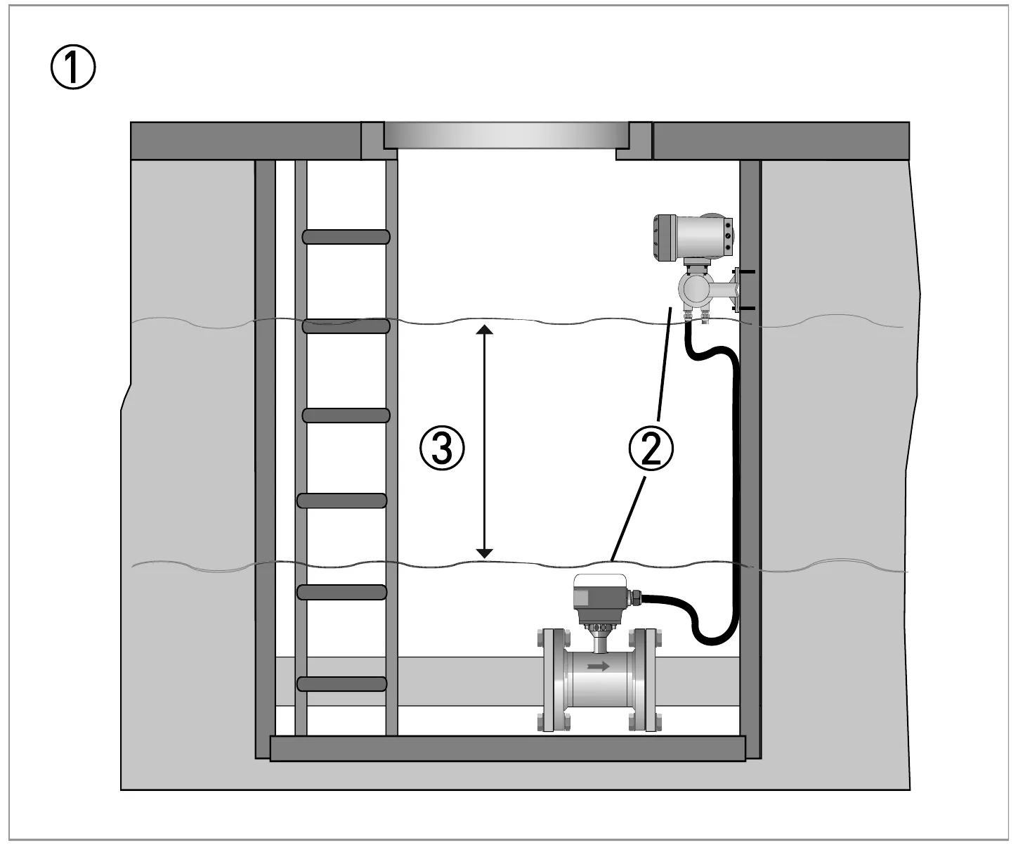
Measuring pit: ① continuous submersion; ② remote version; ③ max. water column 10 m / 33 ft
  1. ①Ngập liên tụcContinuous submersion
  2. ②Bản rờiRemote version
  3. ③Cột nước tối đa 10 mMaximum water column 10 m / 33 ft
Hố đo: ① ngập liên tục; ② bản rời; ③ cột nước tối đa 10 mMeasuring pit: ① continuous submersion; ② remote version; ③ max. water column 10 m / 33 ft MA-S p.20

Đã chọn hộp đấu nối inox – tùy chọn IP68 / NEMA 6P (chỉ có ở bản rời với hộp inox): phù hợp hố đo ngập liên tục, cột nước tối đa 10 m. Xác nhận IP68 trong order code.Stainless connection box selected – IP68 / NEMA 6P option (separate design with stainless box only): suitable for continuously flooded pits, max. 10 m water column. Confirm IP68 in the order code. TD-S p.15MA-S p.20

WARNING
Hộp đấu nối nhôm: cấp bảo vệ tiêu chuẩn IP66/67 – không dùng cho hố đo ngập liên tục. Nếu hố có nguy cơ ngập, cần cấu hình IP68 (hộp inox).Aluminium connection box: standard IP66/67 – not for continuously flooded pits. If flooding is possible, specify IP68 (stainless box). TD-S p.15

Lớp phủ subsoil cho phép chôn trực tiếp khi kết hợp bản IP68.Subsoil coating allows direct burial when combined with the IP68 version. TD-S p.5

Lạc ViệtNước thô đầu vào nhà máy thường có cát, rác, khí hòa tan: ưu tiên đoạn ống thấp hoặc đi lên; bố trí van xả khí ở điểm cao phía trước đồng hồ; có cửa/van xả cặn để vệ sinh tuyến; tránh đặt ngay sau bơm có xâm thực. Hố đo phải thoát nước được và đủ chỗ thao tác bulông DN lớn.Raw water at plant intakes often carries sand, debris and dissolved air: prefer a low or ascending section; put an air release valve at the high point upstream; provide a washout for cleaning; avoid placing the meter right after a cavitating pump. The pit must drain and leave room to work on large-DN bolts.

Ảnh thực tế – theo cấu hình đang chọnIn the field – for the selected configuration
Toàn cảnh hố đo sau lắp đặt
Toàn cảnh hố đo sau lắp đặtMeter chamber overview after installation Ảnh hiện trường thật – Lạc Việt, TP.HCM 2017 · đã chỉnh sáng/làm nétReal site photo – Lạc Việt, HCMC 2017 · brightness/sharpness adjusted

Ảnh thực tế – theo cấu hình đang chọnIn the field – for the selected configuration
OPTIFLUX 2300 F chôn ngầm, IP68 – khai thác nước ngầm dunea (Hà Lan)
OPTIFLUX 2300 F chôn ngầm, IP68 – khai thác nước ngầm dunea (Hà Lan)OPTIFLUX 2300 F buried, IP68 – dunea drinking water abstraction (NL) © KROHNE · làm nét bằng AI, không thêm bớt chi tiếtAI-sharpened, no details added Application p.11–12
OPTIFLUX 2300 W DN900 lớp phủ chôn ngầm – nhà máy nước, Úc
OPTIFLUX 2300 W DN900 lớp phủ chôn ngầm – nhà máy nước, ÚcOPTIFLUX 2300 W DN900 with burial coating – water plant, Australia © KROHNE · làm nét bằng AI, không thêm bớt chi tiếtAI-sharpened, no details added Application p.1–2

MA-S p.19 Chi tiết trong HandbookDetails in the Handbook ↗

Flange deviation: Lmax - Lmin ≤ 0.5 mm / 0.02"
  1. ①LmaxLmax
  2. ②LminLmin
Độ lệch mặt bích: Lmax − Lmin ≤ 0.5 mmFlange deviation: Lmax - Lmin ≤ 0.5 mm / 0.02" MA-S p.19
CAUTION
Độ lệch tối đa giữa hai mặt bích ống: Lmax − Lmin ≤ 0.5 mm.Max. deviation of the pipe flange faces: Lmax - Lmin ≤ 0.5 mm / 0.02". MA-S p.19
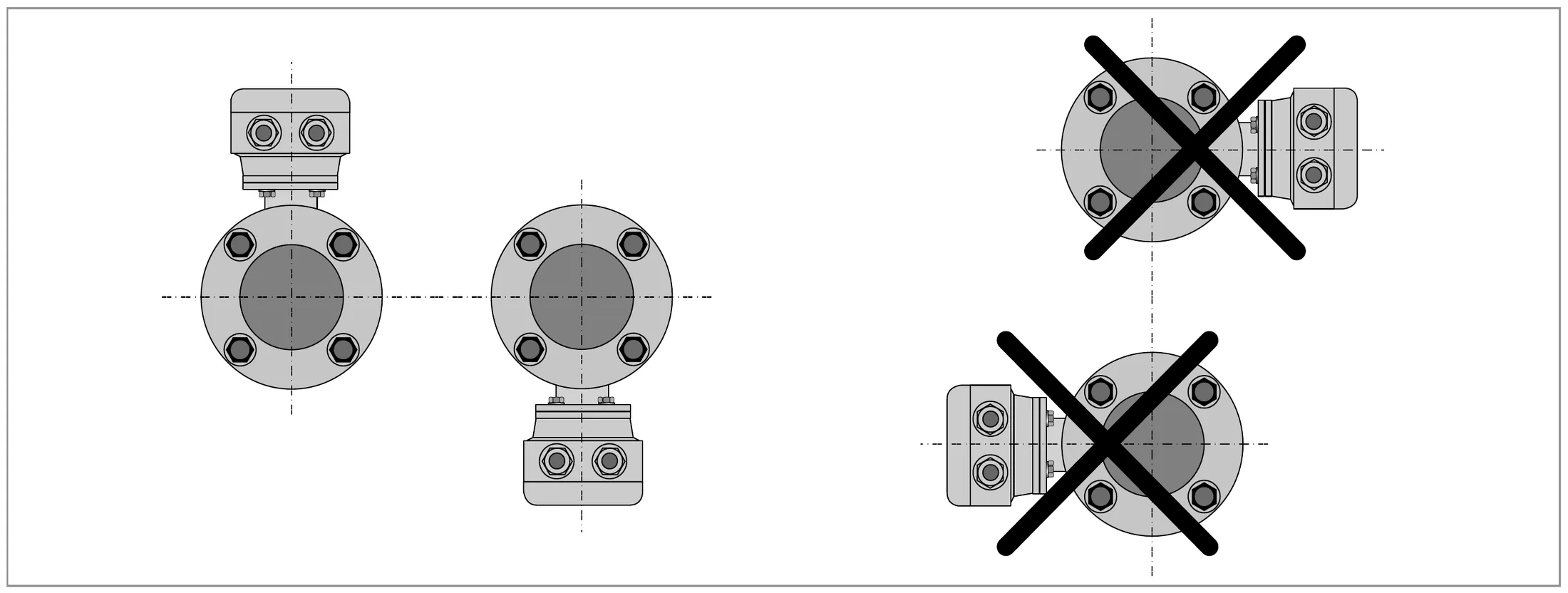
Mounting position: converter/connection box aligned upwards or downwards
  1. ✓1Converter hướng lênSignal converter aligned upwards
  2. ✓2Converter hướng xuốngSignal converter aligned downwards
  3. ✕1Không đúng yêu cầu: converter phải hướng lên hoặc xuốngNot as required: converter must be aligned upwards or downwards
  4. ✕2Không đúng yêu cầu: converter phải hướng lên hoặc xuốngNot as required: converter must be aligned upwards or downwards
Tư thế lắp: hộp đấu nối/converter hướng lên hoặc xuốngMounting position: converter/connection box aligned upwards or downwards MA-S p.19
  • Hộp đấu nối hướng lên hoặc xuống.Connection box aligned upwards or downwards.
  • Cảm biến đồng trục với ống.Flow sensor in line with the pipe axis.
  • Hai mặt bích ống phải song song.Pipe flange faces must be parallel to each other.

MA-S p.19

Lạc ViệtDN lớn: đặt gối đỡ riêng cho ống hai phía (và đỡ thân đồng hồ nếu thiết kế cho phép) – không để tải đường ống treo lên đồng hồ. Nên có khớp tháo lắp (dismantling joint) phía hạ lưu để lắp/tháo và bù sai lệch chiều dài. Khi súc rửa, thử áp tuyến: lắp ống giả (spool) thay đồng hồ.Large DN: support the pipe on both sides independently (and the meter body if the design allows) – never let pipe loads hang on the meter. Fit a dismantling joint downstream for installation/removal and length tolerance. During flushing and pressure testing, install a spool piece instead of the meter.

MA-S p.21–24 Chi tiết trong HandbookDetails in the Handbook ↗

CAUTION
Dùng gioăng phù hợp để không làm hỏng lót. Không nên dùng gioăng spiral wound – có thể làm hỏng lót nghiêm trọng.Use the proper gasket to avoid damaging the liner. Spiral wound gaskets are not advised; they could severely damage the liner. MA-S p.21
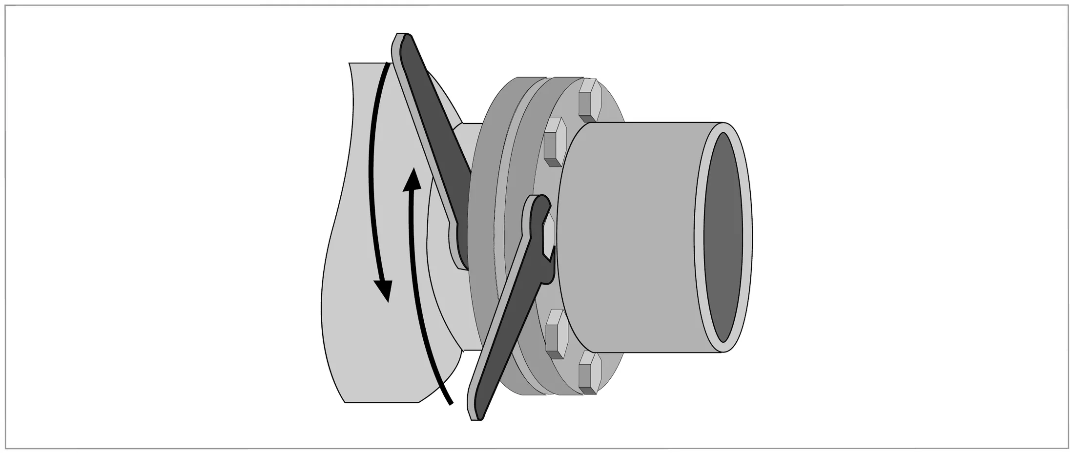
Tightening of bolts
Siết bulôngTightening of bolts MA-S p.21
  1. Luôn siết đều, theo thứ tự chéo đối xứng; không vượt mô-men tối đa.Always tighten uniformly in diagonally opposite sequence; do not exceed the max. torque.
  2. Lần 1: ~50 % mô-men tối đa trong bảng.Step 1: approx. 50% of max. torque given in the table.
  3. Lần 2: ~80 %.Step 2: approx. 80%.
  4. Lần 3: 100 %.Step 3: 100%.

MA-S p.21

Giá trị mô-men là lý thuyết, tính cho điều kiện tối ưu với bích thép carbon; phụ thuộc nhiệt độ, vật liệu bulông, gioăng, chất bôi trơn – chỉ mang tính tham khảo.Torque values are theoretical, calculated for optimum conditions with carbon steel flanges; they depend on temperature, bolt and gasket material, lubricants – indicative only. MA-S p.21–22

Ảnh thực tế – theo cấu hình đang chọnIn the field – for the selected configuration
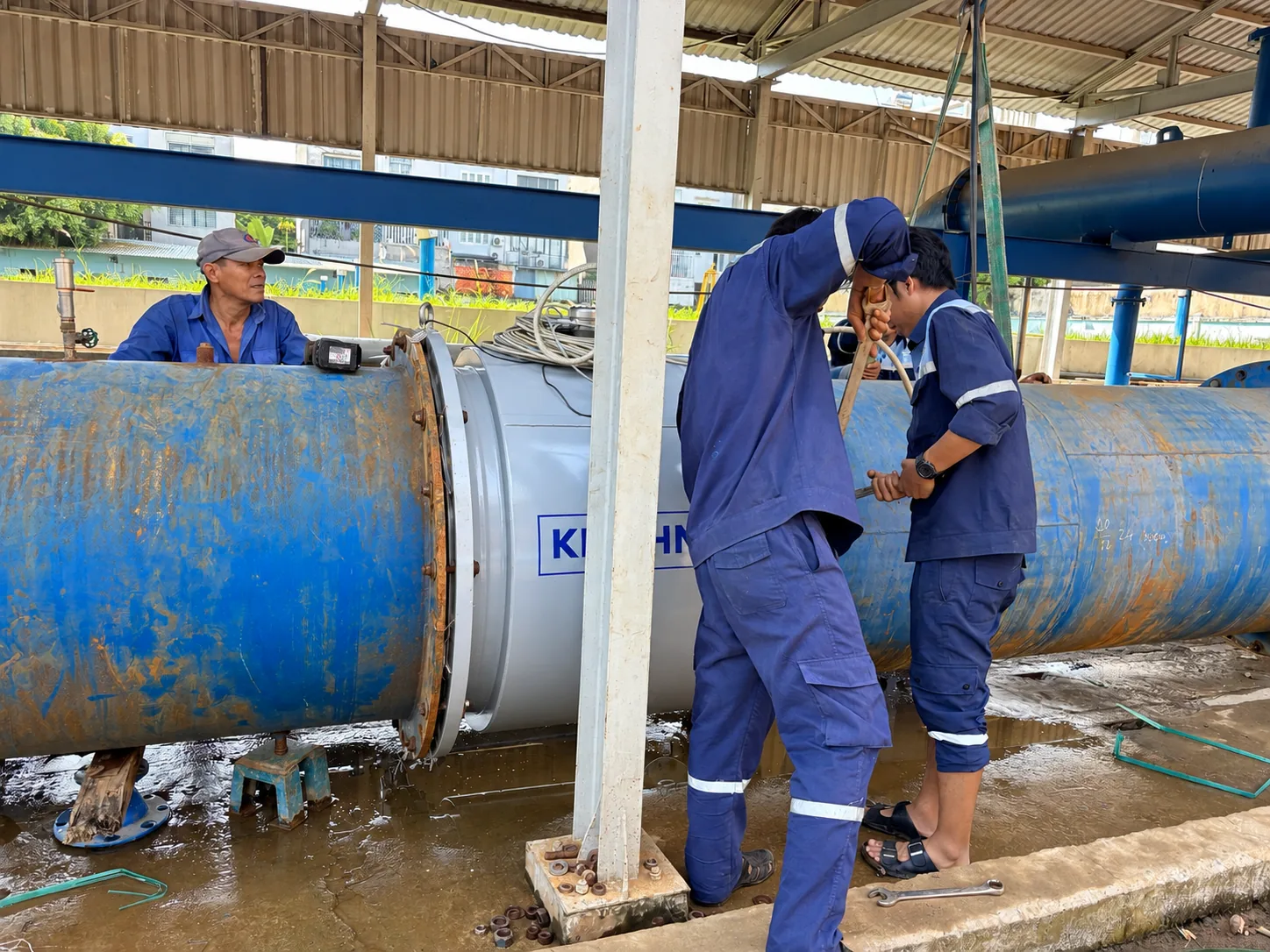
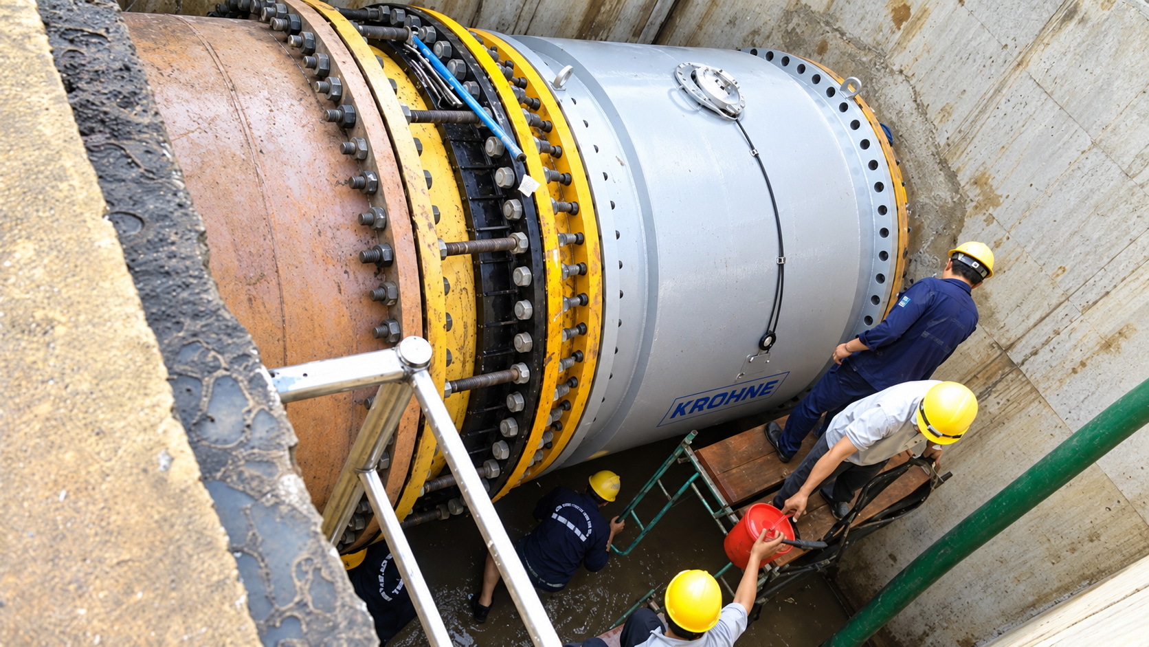
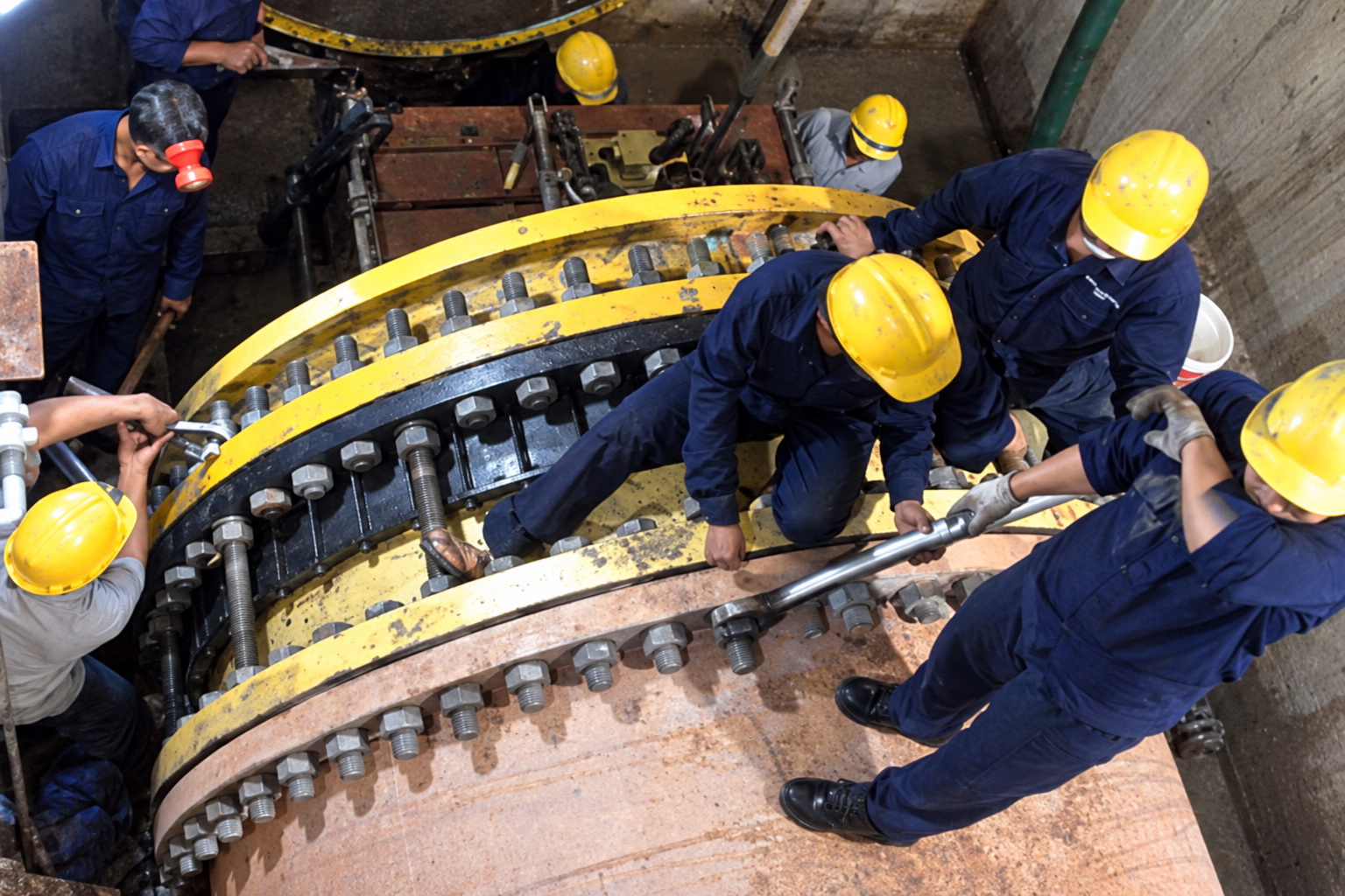
Siết bulông mặt bích
Siết bulông mặt bíchTightening the flange bolts Ảnh hiện trường thật – Lạc Việt, TP.HCM 2017 · đã chỉnh sáng/làm nétReal site photo – Lạc Việt, HCMC 2017 · brightness/sharpness adjusted
Kiểm tra sau lắp đặt
Kiểm tra sau lắp đặtPost-installation check Ảnh hiện trường thật – Lạc Việt, TP.HCM 2017 · đã chỉnh sáng/làm nétReal site photo – Lạc Việt, HCMC 2017 · brightness/sharpness adjusted

MA-S p.25–27MA-C p.25, p.52–53 Chi tiết trong HandbookDetails in the Handbook ↗

DANGER
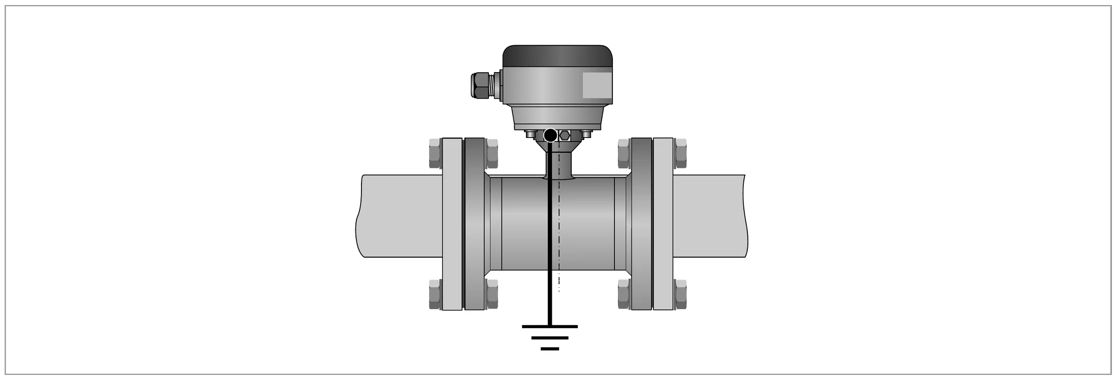
Thiết bị phải được nối đất theo quy định để bảo vệ người khỏi điện giật.The device must be grounded in accordance with regulations to protect personnel against electric shocks. MA-S p.25MA-C p.24
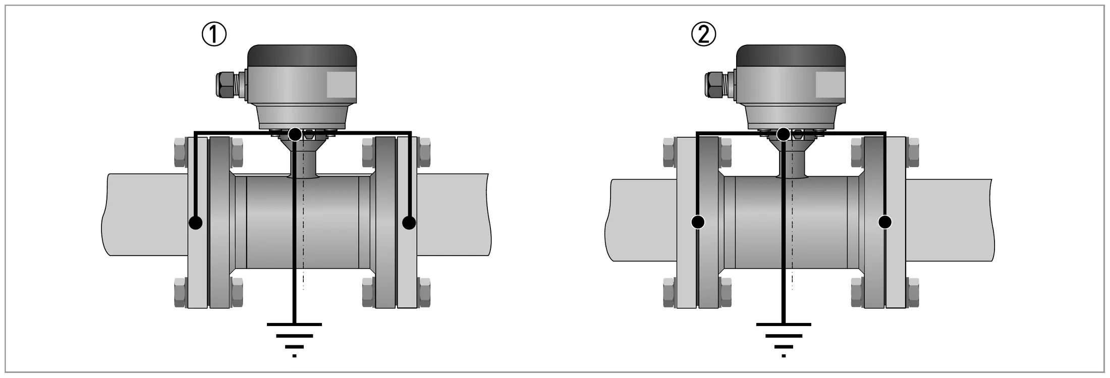
Grounding
  1. 1Ống kim loại không phủ trong: tiếp địa KHÔNG cần vòng tiếp địaMetal pipelines, not internally coated: grounding without grounding rings
  2. 2Ống kim loại có phủ trong và ống không dẫn điện: tiếp địa CÓ vòng tiếp địaInternally coated metal and non-conductive pipelines: grounding with grounding rings
Tiếp địaGrounding MA-S p.25

Ống kim loại không phủ trong: tiếp địa không cần vòng tiếp địa (hình ①).Metal pipelines not internally coated: grounding without grounding rings (figure ①). MA-S p.25

Ống kim loại có phủ trong và ống không dẫn điện: tiếp địa có vòng tiếp địa (hình ②). Vòng tiêu chuẩn: inox; tùy chọn Hastelloy® C, titan, tantalum.Internally coated metal and non-conductive pipelines: grounding with grounding rings (figure ②). Standard rings: stainless steel; options Hastelloy® C, titanium, tantalum. MA-S p.25TD-S p.12

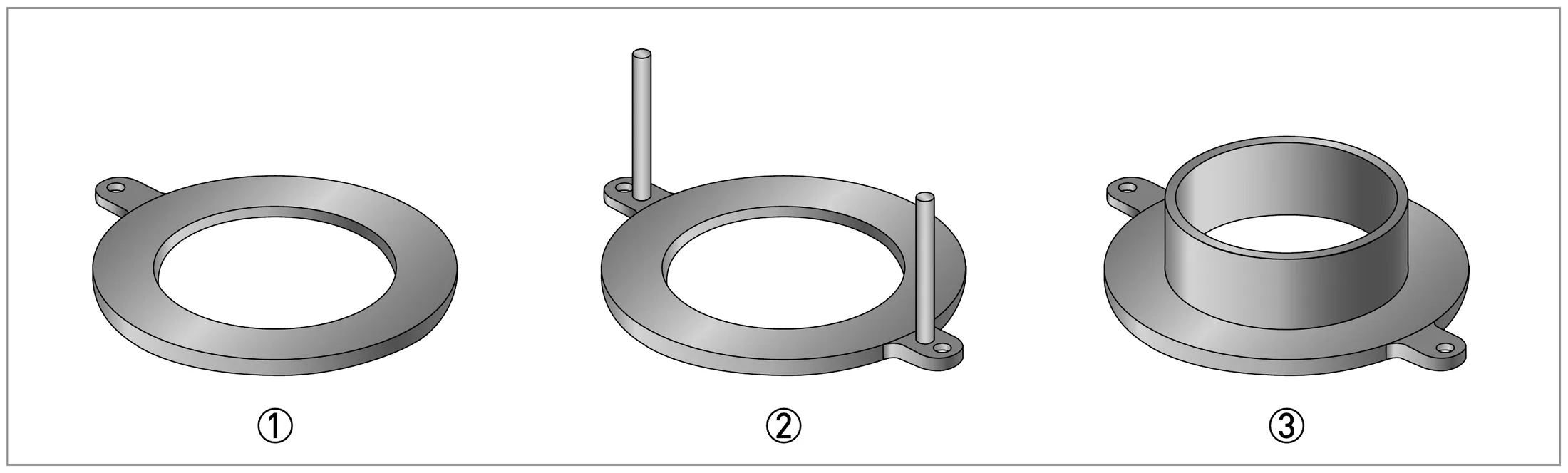
Grounding rings no. 1, 2, 3
  1. ①Vòng tiếp địa số 1Grounding ring number 1
  2. ②Vòng tiếp địa số 2Grounding ring number 2
  3. ③Vòng tiếp địa số 3Grounding ring number 3
Vòng tiếp địa số 1, 2, 3Grounding rings no. 1, 2, 3 MA-S p.26
Vòng tiếp địa – độ dàyGrounding rings – thickness MA-S p.26
LoạiType≤ DN300≤ DN300 / 12"≥ DN350≥ DN350 / 14"Đặc điểmFeature
Số 1No. 13 mm4 mm (tantalum: 0.5 mm)4 mm (tantalum: 0.5 mm)––
Số 2No. 23 mm4 mmChống hỏng mặt bích khi vận chuyển, lắp đặtPrevents damage to the flanges during transport and installation
Số 3No. 33 mm4 mmCó cổ trụ (dài 30 mm cho DN25…150); bảo vệ lót khỏi môi chất mài mònWith cylindrical neck (30 mm for DN25...150); liner protection against abrasive fluids

Virtual reference: bộ khuếch đại đầu vào tạo điện thế tham chiếu theo điện thế của môi chất – bỏ được vòng/điện cực tiếp địa với ống có lót hoặc ống nhựa.Virtual reference: the input amplifier creates a reference from the potential of the medium – grounding rings/electrodes can be omitted on lined or plastic pipes. MA-C p.53

Virtual reference – no grounding rings
Virtual reference – không vòng tiếp địaVirtual reference – no grounding rings MA-S p.27
Điều kiện đo với virtual referenceThresholds for virtual reference MA-C p.53MA-S p.27
Tiêu chíCriterionGiá trịValue
CỡSize≥ DN10
Độ dẫn điệnElectrical conductivity≥ 200 µS/cm
Cáp tín hiệuSignal cableChỉ loại A (DS 300)Use only A (type DS 300)
Chiều dài cápSignal cable length≤ 50 m
CAUTION
Cáp tín hiệu loại B (BTS 300) không dùng được với virtual reference.Signal cable type B (BTS 300) cannot be used with virtual reference. MA-S p.27MA-C p.25
  • Cảm biến nối đất qua dây tiếp địa chức năng FE; dây này không được mang điện áp nhiễu.The sensor is grounded by a functional grounding conductor FE, which must not transmit interference voltages.
  • Không dùng chung dây tiếp địa này để nối đất thiết bị điện khác.Do not use this grounding cable to ground other electrical devices at the same time.

MA-C p.52

CAUTION
Không được có chênh lệch điện thế giữa cảm biến và vỏ/đất bảo vệ của converter.There should be no difference in potential between the flow sensor and the housing or protective earth of the signal converter. MA-C p.52

Lạc ViệtỐng thép/gang có lót xi măng hoặc sơn epoxy trong, ống HDPE/uPVC thuộc nhóm "có phủ trong / không dẫn điện" → cần vòng tiếp địa hoặc virtual reference. Đo kiểm điện trở nối đất khi nghiệm thu.Steel/ductile-iron pipes with cement or epoxy lining and HDPE/uPVC pipes belong to the "coated / non-conductive" group → grounding rings or virtual reference are needed. Measure the earthing resistance at commissioning.

Ảnh thực tế – theo cấu hình đang chọnIn the field – for the selected configuration
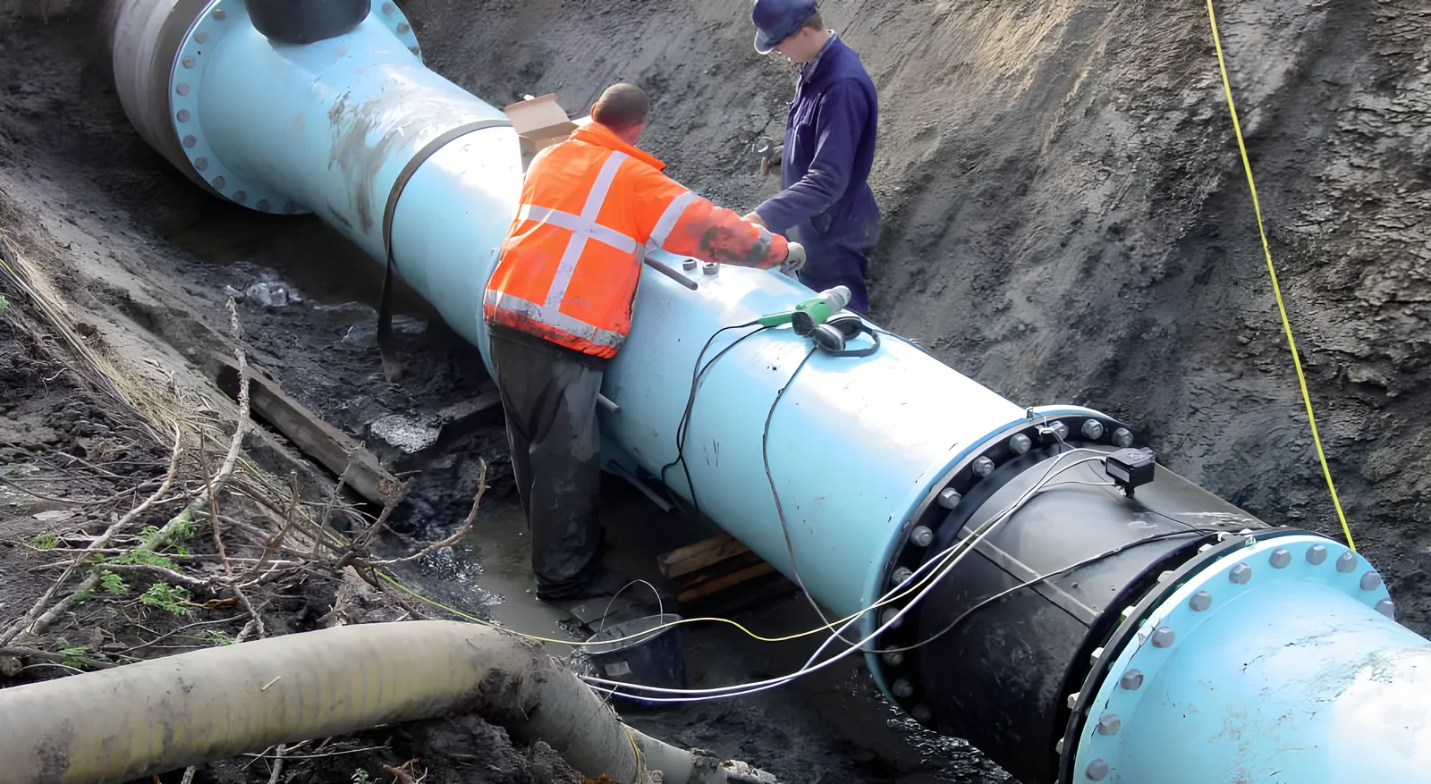
OPTIFLUX 2300 W DN800 tuyến nước chính, Virtual Reference – Duisburg
OPTIFLUX 2300 W DN800 tuyến nước chính, Virtual Reference – DuisburgOPTIFLUX 2300 W DN800 on a main water line, Virtual Reference – Duisburg © KROHNE · làm nét bằng AI, không thêm bớt chi tiếtAI-sharpened, no details added Application p.15–16

MA-C p.14, p.18–21 Chi tiết trong HandbookDetails in the Handbook ↗

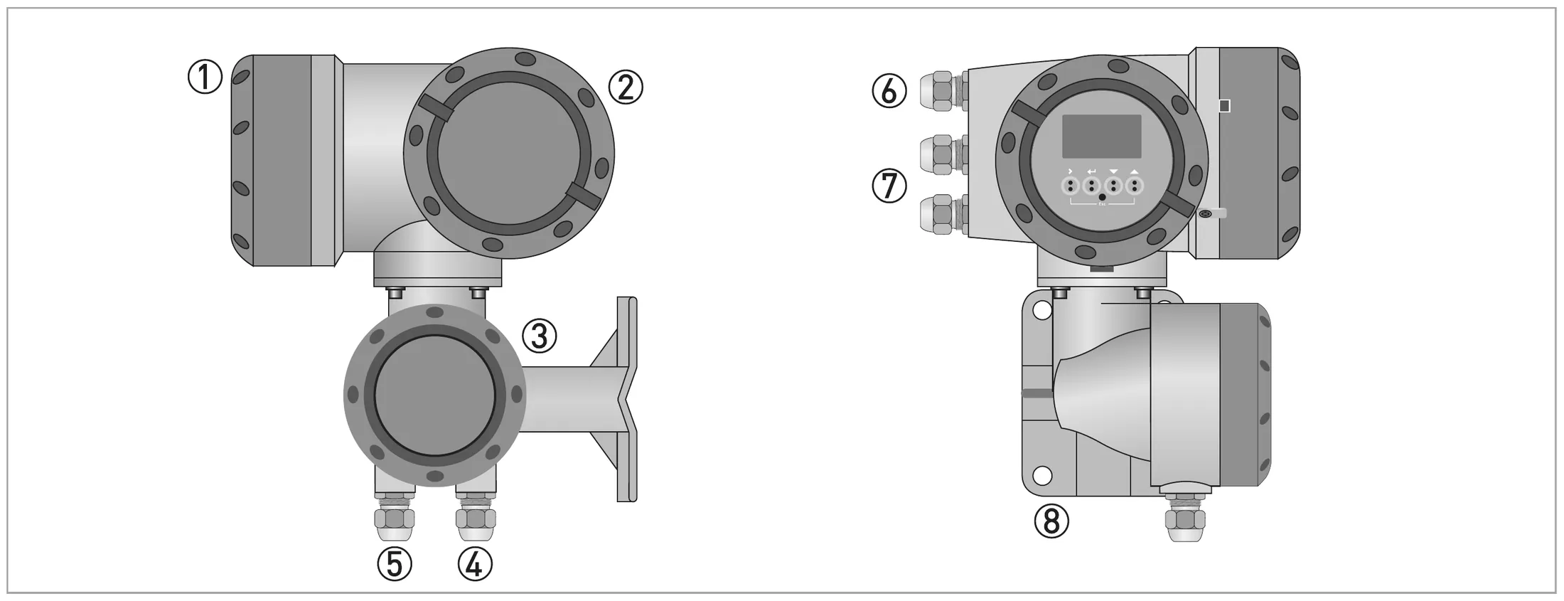
Construction of the field housing (F)
  1. 1Nắp ngăn điện tử và màn hìnhCover for electronics and display
  2. 2Nắp ngăn đấu nguồn và I/OCover for power supply and inputs/outputs terminal compartment
  3. 3Nắp ngăn đấu cáp cảm biếnCover for flow sensor terminal compartment
  4. 4Lỗ cáp tín hiệu cảm biếnCable entry for flow sensor signal cable
  5. 5Lỗ cáp dòng kích từCable entry for flow sensor field current cable
  6. 6Lỗ cáp nguồnCable entry for power supply
  7. 7Lỗ cáp I/OCable entry for inputs and outputs
  8. 8Tấm gá lắp lên ống/tườngMounting plate for pipe and wall mounting
Cấu tạo vỏ field (F)Construction of the field housing (F) MA-C p.14
  • Đủ khoảng trống hai bên.Adequate space to the sides.
  • Bức xạ nhiệt không được làm vỏ vượt nhiệt độ môi trường cho phép – lắp mái che nắng nếu cần.Radiated heat must not raise the housing above the max. ambient temperature – fit a sun shade if necessary.
  • Tránh rung mạnh; che nắng/UV; tránh vòi phun áp lực cao gần thiết bị.Avoid intense vibrations; protect from solar heat/UV; avoid high pressure jets close to the device.

MA-C p.18

Lắp lên ốngPipe mounting

  1. Cố định giá gá converter lên ống.Fix the mounting bracket of the converter to the pipe.
  2. Siết giá gá bằng U-bolt và long đen tiêu chuẩn.Fasten the bracket using standard U-bolts and washers.
  3. Siết đai ốc.Tighten the nuts.

MA-C p.19

Lắp lên tườngWall mounting

  1. Khoan lỗ theo tấm gá (kích thước tấm gá: MA-C p.160).Prepare the holes with the mounting plate (dimensions: MA-C p.160).
  2. Bắt chắc tấm gá lên tường.Fasten the mounting plate securely to the wall.
  3. Bắt giá converter vào tấm gá bằng đai ốc và long đen.Screw the converter bracket to the plate with nuts and washers.

MA-C p.20

Khoảng cách khi lắp nhiều converter cạnh nhauSpacing when mounting several converters side by side MA-C p.20, p.23
VỏHousingKhoảng cáchDistance
Fa ≥ 600 mm · b ≥ 250 mm
Wa ≥ 240 mm
INFORMATION
Mỗi lần mở nắp: vệ sinh và bôi mỡ ren (mỡ không chứa nhựa và axit); kiểm tra gioăng vỏ sạch, đúng vị trí, không hỏng.Each time a cover is opened, clean and grease the thread (resin-free and acid-free grease only); check the housing gasket is fitted, clean and undamaged. MA-C p.14, p.21

Converter bản rời IFC 300 F: IP66/67, NEMA 4/4X – đặt ở chỗ khô trên tường hố đo hoặc nhà trạm để đọc màn hình.Remote IFC 300 F converter: IP66/67, NEMA 4/4X – install in a dry area on the pit wall or in the station building for read-out. TD-S p.39

Lạc ViệtĐặt IFC 300 F cao hơn mức ngập lớn nhất của hố, có mái che nắng mưa, gần tủ điện/RTU; tổng chiều dài cáp tính cả đoạn đi trong máng và vòng cáp dự phòng.Place the IFC 300 F above the highest flood level, with a sun/rain shade, near the panel/RTU; count cable length including trays and spare loops.

Ảnh thực tế – theo cấu hình đang chọnIn the field – for the selected configuration
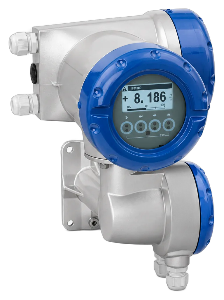
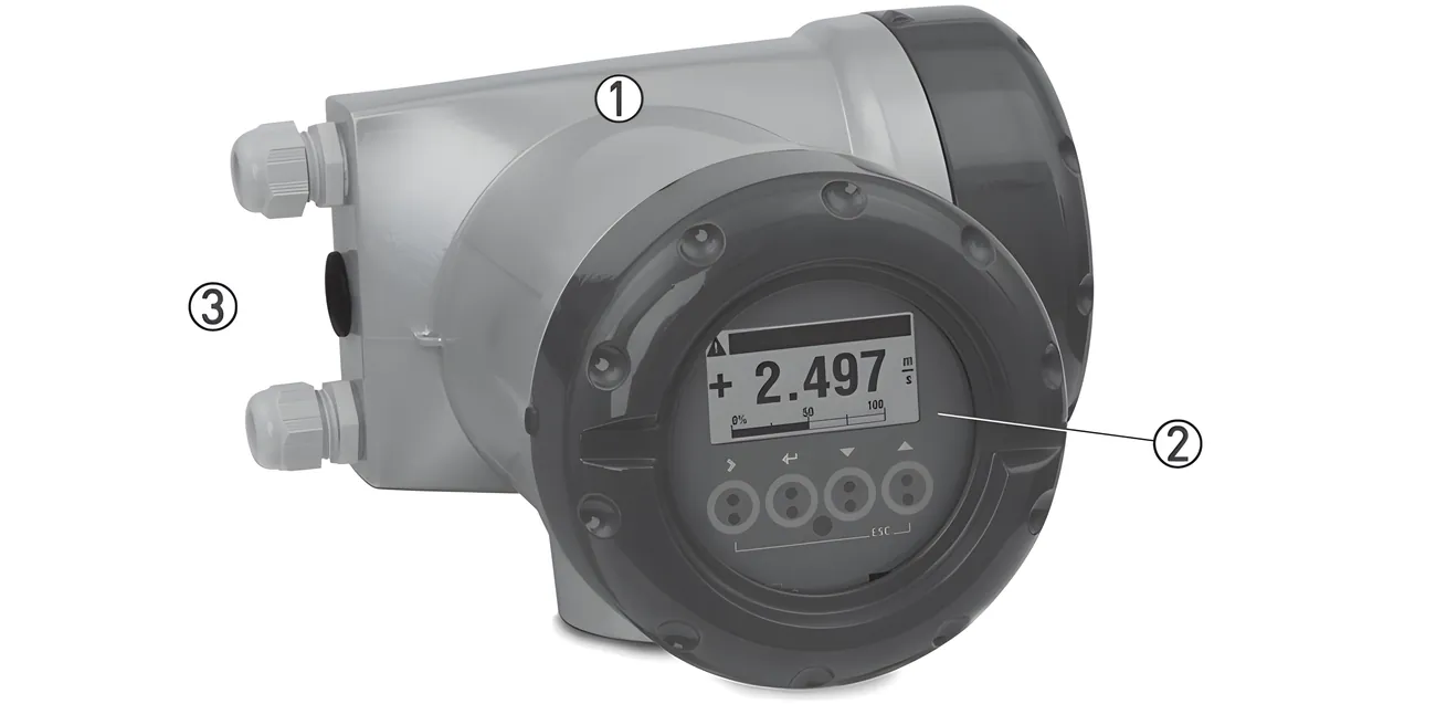
Converter IFC 300 F – vỏ field (bản rời)
Converter IFC 300 F – vỏ field (bản rời)IFC 300 F – field housing (remote) © KROHNE TD-C p.5

MA-C p.17, p.24, p.53–55 Chi tiết trong HandbookDetails in the Handbook ↗

DANGER
Mọi công việc đấu điện chỉ thực hiện khi đã cắt nguồn. Lưu ý điện áp trên nameplate!All work on the electrical connections may only be carried out with the power disconnected. Take note of the voltage on the nameplate! MA-C p.24
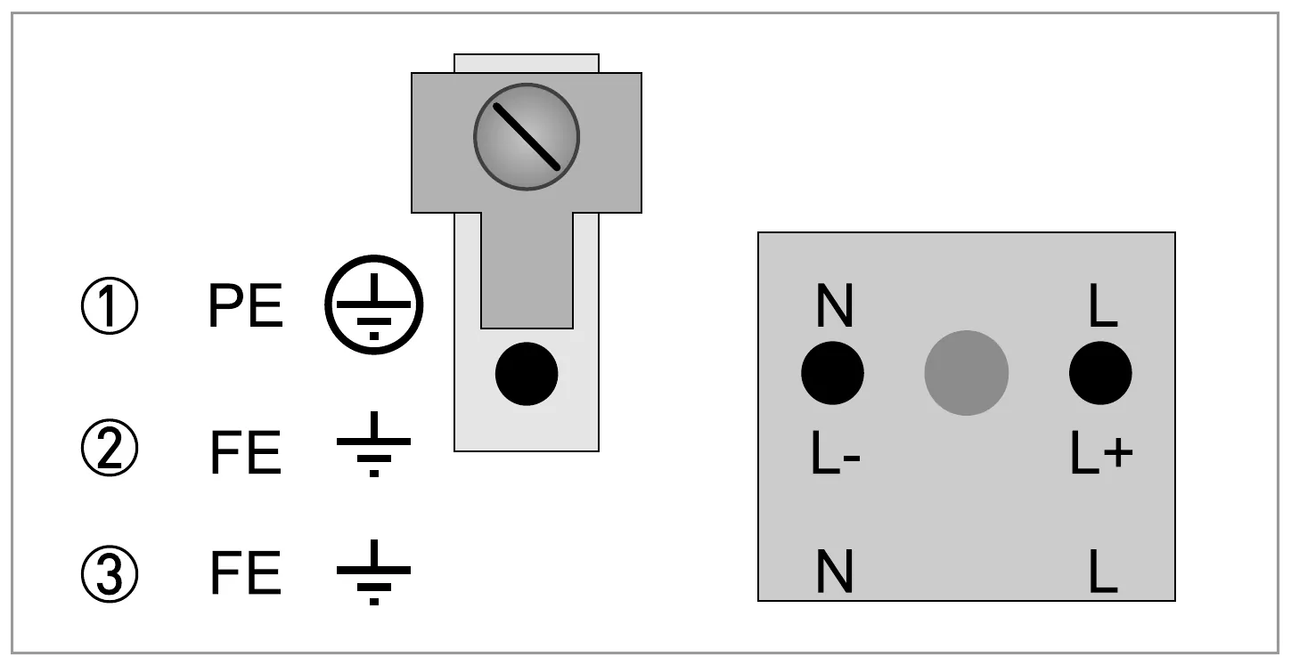
Nguồn cấp IFC 300IFC 300 power supply MA-C p.54–55
Phương ánVariantDải dung saiToleranceCông suấtConsumptionGhi chúNote
100…230 VAC, 50…60 Hz-15% / +10%22 VA240 VAC + 5 % nằm trong dung sai; PE vào cực kẹp U240 VAC + 5% included; PE to U-clamp terminal
12…24 VDC24 VDC: -55% / +30%24 VDC: -55% / +30%12 W12 VDC − 10 % nằm trong dung sai12 VDC - 10% included
24 VAC/DCAC: -15% / +10% · DC: -25% / +30%22 VA / 12 W12 V không nằm trong dung sai12 V not included
Power supply connection (excluding rack housing)
  1. 1① 100…230 VAC (−15 % / +10 %), 22 VA – PE① 100...230 VAC (-15% / +10%), 22 VA – PE
  2. 2② 24 VDC (−55 % / +30 %), 12 W – FE② 24 VDC (-55% / +30%), 12 W – FE
  3. 3③ 24 VAC/DC (AC −15 % / +10 %; DC −25 % / +30 %), 22 VA hoặc 12 W – FE③ 24 VAC/DC (AC: -15% / +10%; DC: -25% / +30%), 22 VA or 12 W – FE
Đấu nguồn (trừ bản rack)Power supply connection (excluding rack housing) MA-C p.55
  • Lắp cầu chì (IN ≤ 16 A) và thiết bị cách ly (công tắc/CB) có ghi nhãn là thiết bị cách ly của đồng hồ này.Provide fuse protection (IN ≤ 16 A) and a separator (switch, circuit breaker) marked as the separator for this device.
  • Mạch nguồn: quá áp cấp III; mạch ngõ ra: cấp II.Supply circuits: overvoltage category III; output circuits: category II.

MA-C p.53–54

100…230 VAC: đấu dây bảo vệ PE vào cực kẹp chữ U riêng trong ngăn đấu.100...230 VAC: connect protective ground PE to the separate U-clamp terminal in the terminal compartment. MA-C p.54

Nguồn DC / 24 VAC: nối đất chức năng FE (theo nameplate I/O: PE cho ≥ 24 VAC; FE cho ≤ 24 VAC và DC).DC / 24 VAC supply: functional earth FE (I/O nameplate: PE for ≥ 24 VAC; FE for ≤ 24 VAC and DC). MA-C p.17, p.55

MA-C p.25–50 Chi tiết trong HandbookDetails in the Handbook ↗

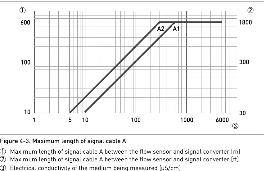
Max. length of cable A vs conductivity – OPTIFLUX 2000 F DN200...2000 uses curve A2
Chiều dài tối đa cáp A theo độ dẫn điện – OPTIFLUX 2000 F DN200…2000 dùng đường cong A2Max. length of cable A vs conductivity – OPTIFLUX 2000 F DN200...2000 uses curve A2 TD-C p.35
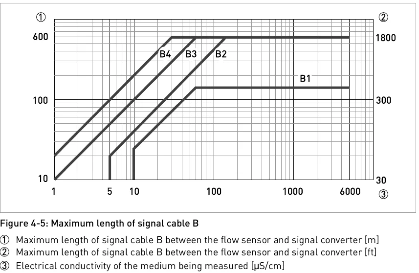
Max. length of cable B vs conductivity – OPTIFLUX 2000 F DN200...2000 uses curve B4
Chiều dài tối đa cáp B theo độ dẫn điện – OPTIFLUX 2000 F DN200…2000 dùng đường cong B4Max. length of cable B vs conductivity – OPTIFLUX 2000 F DN200...2000 uses curve B4 TD-C p.37
  • Cố định cáp bằng kẹp; được phép đặt trong nước hoặc chôn đất.Lay the cable with fastening elements; laying in water or in the ground is permissible.
  • Bán kính uốn ≥ 50 mm.Bending radius ≥ 50 mm / 2".

MA-C p.27, p.33

Cáp kích từ C – tiết diện theo chiều dàiField current cable C – cross-section by length MA-C p.37
Chiều dàiLengthTiết diện CuCross-section CuAWGAWG
0…150 m3 x 0.75 mm²3 x 18
150…300 m3 x 1.5 mm²3 x 14
300…600 m3 x 2.5 mm²3 x 12
DANGER
Cáp kích từ C: cáp đồng 3 lõi không bọc chống nhiễu là đủ. Nếu dùng cáp có chống nhiễu, lưới chống nhiễu KHÔNG được đấu trong vỏ converter.Field current cable C: a non-shielded 3-wire copper cable is sufficient. If a shielded cable is used, the shield must NOT be connected in the converter housing. MA-C p.25, p.37

Chuẩn bị đầu cápPreparing cable ends

Kích thước tuốt cápStripping dimensions MA-C p.29–41
Cáp / đầuCable / endVỏHousingaabb
A – converterA – converterF80 mm10 mm
A – converterA – converterW80 mm–
B – converterB – converterF80 mm10 mm
B – converterB – converterW80 mm–
A / B – cảm biếnA / B – sensorHộp đấu cảm biếnSensor box50 mm10 mm
C – converterC – converterF / W80 mm–
C – cảm biếnC – sensorHộp đấu cảm biếnSensor box50 mm–
  1. Tuốt cáp theo kích thước a; (vỏ F) cắt lưới chống nhiễu ngoài theo b và lật ngược lên vỏ cáp.Strip to dimension a; (F housing) trim the outer shield to b and pull it over the outer sheath.
  2. Cắt lớp chống nhiễu trong và dây thoát (6) – không làm hỏng dây thoát (1).Cut off the inner shield and drain wire (6) – do not damage drain wire (1).
  3. Luồn ống cách điện PVC lên dây thoát (1).Slide a PVC insulating tube over drain wire (1).
  4. Bấm đầu cos DIN 46228: E 1.5-8 cho dây (1); E 0.5-8 cho các lõi.Crimp DIN 46228 ferrules: E 1.5-8 on drain wire (1); E 0.5-8 on the conductors.
  5. Lồng ống co nhiệt lên đầu cáp đã chuẩn bị.Pull heat-shrinkable tubing over the prepared cable.

MA-C p.29–35

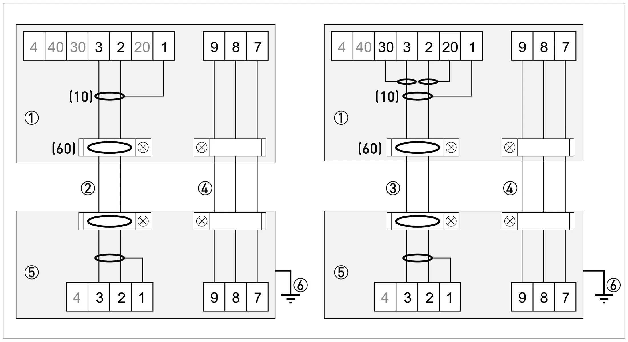
Bảng màu dây & cực đấuWire colours & terminals

Cáp tín hiệu A (DS300-2)Signal cable A (DS300-2) MA-C p.43, p.45
Màu dâyWire colourSố dâyWire no.Cực converterConverter terminalChức năngFunction
TrắngWhite22Điện cực 1Sensor electrode 1
ĐỏRed33Điện cực 2Sensor electrode 2
Dây thoát lưới trongBraided shield drain wire[1]1Chống nhiễu trong cho điện cực 1, 2Inner shield for electrode 1 and 2
Lưới ngoàiBraided shield[60] / [6]F: kẹp giữ cáp · W: kẹp vỏ (đầu cos cắm)F: housing clip strain relief · W: housing clip (push-on connector)Chống nhiễu ngoàiOuter shield
Cáp tín hiệu B (BTS300-2)Signal cable B (BTS300-2) MA-C p.44, p.46
Màu dâyWire colourSố dâyWire no.Cực converterConverter terminalChức năngFunction
TrắngWhite22Điện cực 1Sensor electrode 1
Dây thoátStranded drain wire[20]20Bootstrap shield điện cực 1Bootstrap shield for electrode 1
ĐỏRed33Điện cực 2Sensor electrode 2
Dây thoátStranded drain wire[30]30Bootstrap shield điện cực 2Bootstrap shield for electrode 2
Dây thoát lưới trongBraided shield drain wire11Chống nhiễu trongInner shield
Lưới ngoàiBraided shield[60] / [6]F: kẹp giữ cáp · W: kẹp vỏ (đầu cos cắm)F: housing clip strain relief · W: housing clip (push-on connector)Chống nhiễu ngoài (3 lớp)Outer shield for triple shielding
Cáp kích từ C (cáp cuộn)Field current cable C (coil cable) MA-C p.44, p.46
Màu dâyWire colourSố dâyWire no.Cực converterConverter terminalChức năngFunction
TrắngWhite77Cuộn 1Coil 1
Xanh láGreen88Cuộn 2Coil 2
ĐỏRed99Nhánh giữa cuộn 1 và 2 (tùy chọn)Middle branch coil 1 and coil 2 (optional)
Lưới bọcBraided shield–KHÔNG ĐẤUDO NOT CONNECTGiáp chỉ bảo vệ cơ học (tùy chọn)Braided armour only for mechanical protection (optional)
Connection diagram for flow sensor – field housing (F)
  1. 1Ngăn đấu cáp tín hiệu và kích từ trong converterTerminal compartment in converter housing for signal and field current cable
  2. 2Cáp tín hiệu A (DS 300)Signal cable A (type DS 300)
  3. 3Cáp tín hiệu B (BTS 300)Signal cable B (type BTS 300)
  4. 4Cáp kích từ C (LiYCY)Field current cable C (type LiYCY)
  5. 5Hộp đấu nối cảm biếnConnection box of flow sensor
  6. 6Tiếp địa chức năng FEFunctional ground FE
  7. 10(10) lớp chống nhiễu trong(10) inner cable shield
  8. 60(60) lớp chống nhiễu ngoài – kẹp vào vỏ qua kẹp giữ cáp(60) outer cable shield – clamped to the housing via strain relief
Sơ đồ đấu cảm biến – vỏ field (F)Connection diagram for flow sensor – field housing (F) MA-C p.49
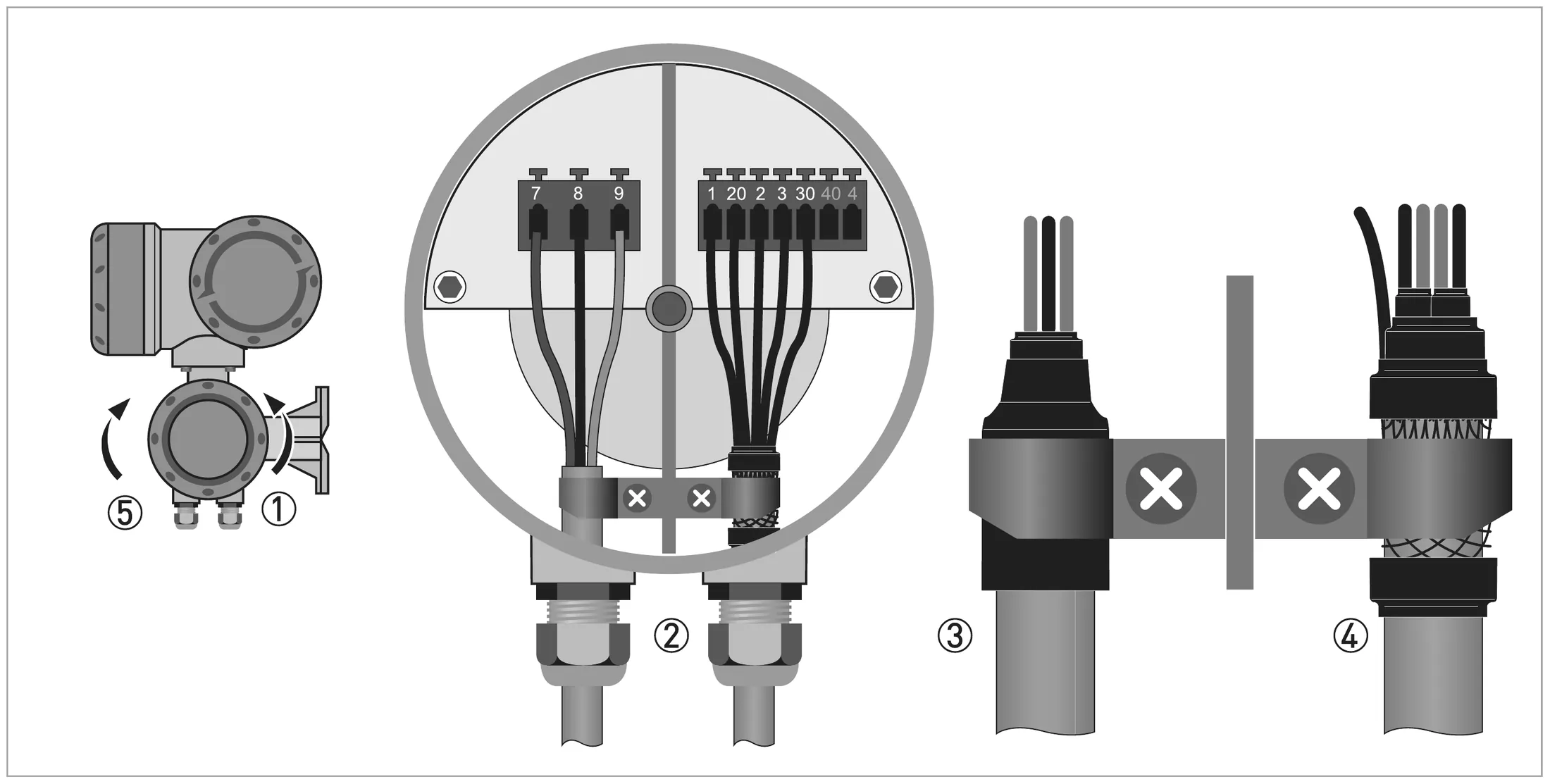
Connecting signal and field current cables – field housing (numbers = steps)
  1. 1Tháo nắp ngăn đấu cảm biếnUnscrew the terminal compartment cover
  2. 2Luồn cáp qua lỗ cáp, đấu dây thoát và lõiPass the cables through the cable entries and connect drain wires and conductors
  3. 3Kẹp cáp kích từ – không đấu lưới chống nhiễuSecure the field current cable with the clip – shield NOT connected
  4. 4Kẹp cáp tín hiệu – nối lưới ngoài vào vỏSecure the signal cable with the clip – connects the outer shield
  5. 5Lắp lại nắp, siết bằng tayRe-fit the cover and tighten it by hand
Đấu cáp tín hiệu và cáp kích từ – vỏ field (số trên hình = bước thao tác)Connecting signal and field current cables – field housing (numbers = steps) MA-C p.43
  1. Tháo nắp ngăn đấu cảm biến.Unscrew the terminal compartment cover.
  2. Luồn cáp tín hiệu và cáp kích từ qua ốc siết cáp, đấu dây thoát và lõi theo bảng.Pass the signal and field current cables through the cable entries and connect drain wires and conductors per the tables.
  3. Cố định cáp kích từ bằng kẹp – không đấu lưới chống nhiễu (nếu có).Secure the field current cable with the clip – any shield must NOT be connected.
  4. Cố định cáp tín hiệu bằng kẹp – kẹp đồng thời nối lớp chống nhiễu ngoài vào vỏ.Secure the signal cable with the clip – this also connects the outer shield to the housing.
  5. Lắp nắp, siết bằng tay.Re-fit the cover and tighten it by hand.

MA-C p.43

INFORMATION
Nên luồn cáp trong ống bảo vệ. Bản field IP68: cáp được đấu và bịt kín IP68 bằng nhựa hai thành phần giao kèm.Place cables in a protective tube. IP68 field version: cables are connected and sealed to IP68 with the separately delivered two-component resin. MA-S p.20
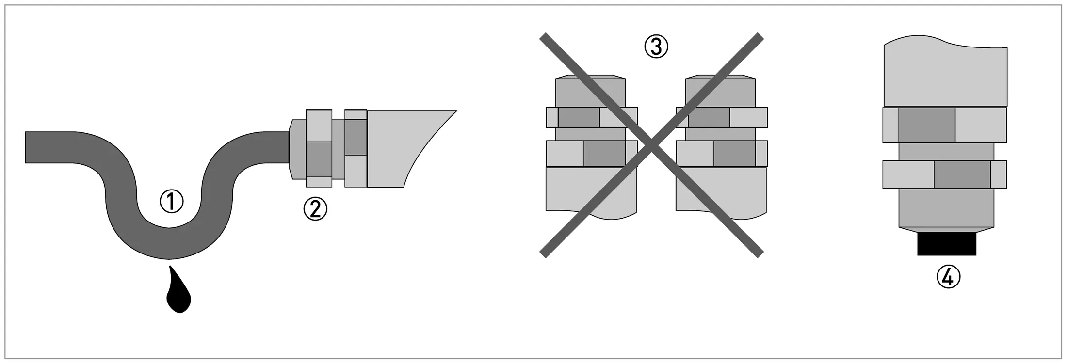
Protect housing from dust and water: ① cable loop, ② tighten gland, ③ entries never upwards, ④ plug unused entries
  1. ①Uốn cáp thành vòng ngay trước vỏLay the cable in a loop just before the housing
  2. ②Siết chặt ốc của lỗ luồn cápTighten the screw connection of the cable entry securely
  3. ③Không lắp vỏ với lỗ luồn cáp hướng lênNever mount the housing with the cable entries facing upwards
  4. ④Bịt lỗ luồn cáp không dùng bằng nút bịtSeal cable entries that are not needed with a plug
Bảo vệ vỏ khỏi bụi và nước: ① vòng cáp, ② siết ốc cáp, ③ không để lỗ cáp hướng lên, ④ bịt lỗ thừaProtect housing from dust and water: ① cable loop, ② tighten gland, ③ entries never upwards, ④ plug unused entries MA-C p.68
  1. Tạo vòng cáp (võng) ngay trước vỏ để nước chảy xuống.Lay the cable in a loop just before the housing.
  2. Siết chặt ốc siết cáp.Tighten the cable entry screw connection securely.
  3. Không bao giờ lắp vỏ với lỗ cáp hướng lên trên.Never mount the housing with cable entries facing upwards.
  4. Bịt các lỗ cáp không dùng bằng nút.Seal unused cable entries with a plug.

MA-C p.68

Ảnh thực tế – theo cấu hình đang chọnIn the field – for the selected configuration
Hộp đấu nối trên sensor
Hộp đấu nối trên sensorConnection box on the sensor Ảnh hiện trường thật – Lạc Việt, TP.HCM 2017 · đã chỉnh sáng/làm nétReal site photo – Lạc Việt, HCMC 2017 · brightness/sharpness adjusted

Ảnh thực tế – theo cấu hình đang chọnIn the field – for the selected configuration

Cảm biến OPTIFLUX 2000 bản IP68, hộp đấu nối inox (cho bản F)
Cảm biến OPTIFLUX 2000 bản IP68, hộp đấu nối inox (cho bản F)OPTIFLUX 2000 sensor, IP68 version with stainless steel connection box (for F) © KROHNE · làm nét bằng AI, không thêm bớt chi tiếtAI-sharpened, no details added TD-S p.5

MA-C p.56–89TD-C p.20, p.46–48 Chi tiết trong HandbookDetails in the Handbook ↗
INFORMATION
Phiên bản I/O thực tế ghi trên nhãn dán ở nắp ngăn đấu dây và trong mã CG (B3.1 / C5.1.2). Đấu active/passive đúng phiên bản.The installed I/O version is on the sticker in the terminal compartment cover and in the CG number (B3.1 / C5.1.2). Wire active/passive accordingly. MA-C p.61–65
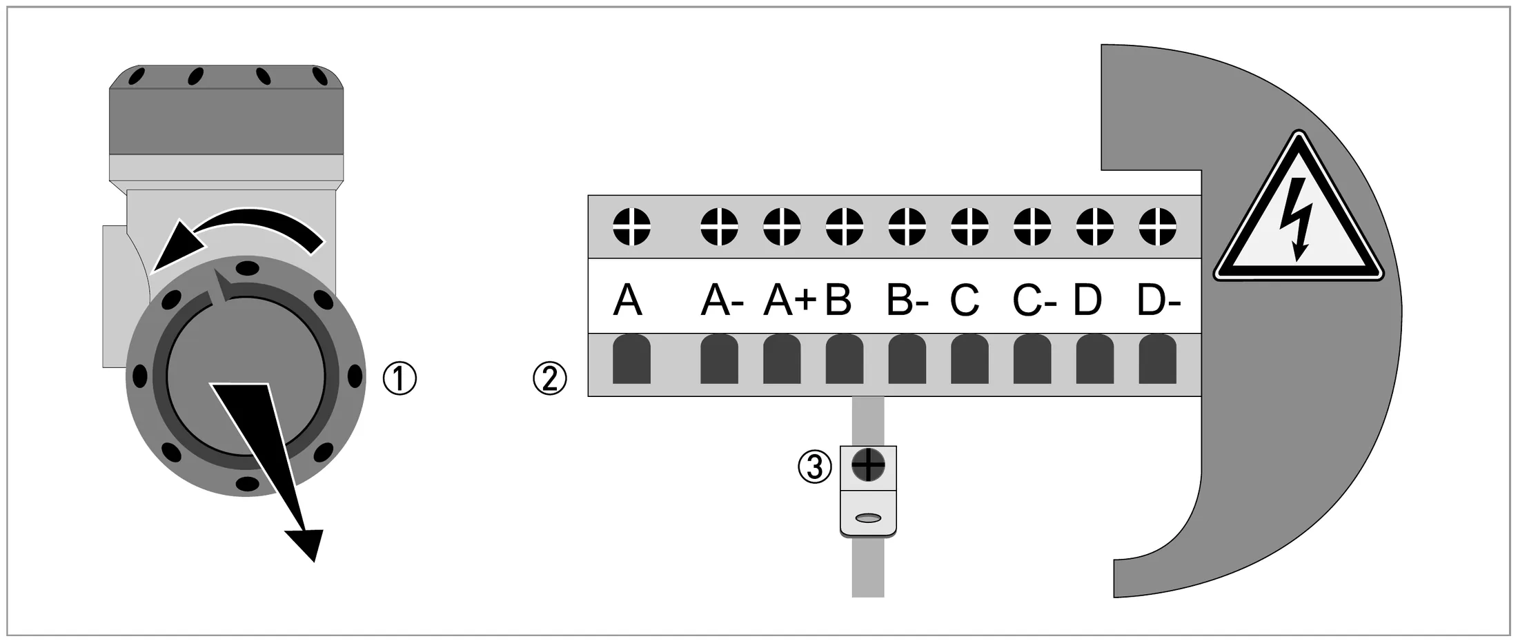
Terminal compartment for inputs and outputs – field housing
  1. 1Mở nắp vỏOpen the housing cover
  2. 2Luồn cáp qua lỗ cáp, đấu vào cực A, A−, A+, B, B−, C, C−, D, D−Push the cable through the entry and connect to terminals A, A-, A+, B, B-, C, C-, D, D-
  3. 3Đấu lưới chống nhiễu nếu cầnConnect the shield if necessary
Ngăn đấu I/O – vỏ fieldTerminal compartment for inputs and outputs – field housing MA-C p.66
Basic I/O – CG …100 (bảng cố định)Basic I/O – CG …100 (fixed table) TD-C p.46MA-C p.58
CựcTerminalsI/OI/ODùng choUsed for
A+ / AIa + HART® active4–20 mA active – converter cấp nguồn vòng dòng4–20 mA active – converter powers the loop
A / A−Ip + HART® passive4–20 mA passive – nguồn vòng dòng từ PLC/RTU4–20 mA passive – loop powered by the PLC/RTU
B / B−Sp / Cp passiveStatus output hoặc control input (đổi được)Status output or control input (changeable)
C / C−Sp passiveStatus output / limit switchStatus output / limit switch
D / D−Pp / Sp passiveNgõ ra xung về bộ đếm/PLC (hoặc status)Pulse output to counter/PLC (or status)
WARNING
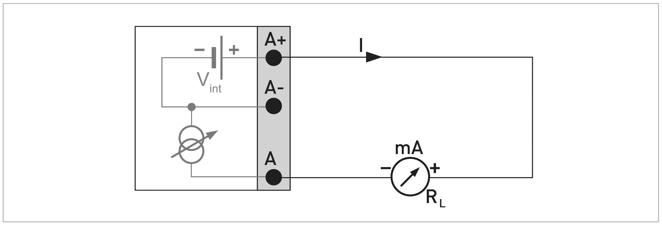
Không dùng đồng thời cực A+ và A−: hệ thống sẽ hỏng do điện áp 24 VDC và dòng đỉnh 1 A.Do not use the terminals A+ and A- at the same time. The system will be damaged by 24 VDC and a 1 A peak current. MA-C p.17
Current output active Ia (Basic I/O): Vint,nom = 24 VDC, I ≤ 22 mA, RL ≤ 1 kΩ – do not connect A+ and A- directly to an external input
Ngõ ra dòng active Ia (Basic I/O): Vint,nom = 24 VDC, I ≤ 22 mA, RL ≤ 1 kΩ – không nối A+ và A− trực tiếp vào ngõ vào ngoàiCurrent output active Ia (Basic I/O): Vint,nom = 24 VDC, I ≤ 22 mA, RL ≤ 1 kΩ – do not connect A+ and A- directly to an external input MA-C p.71
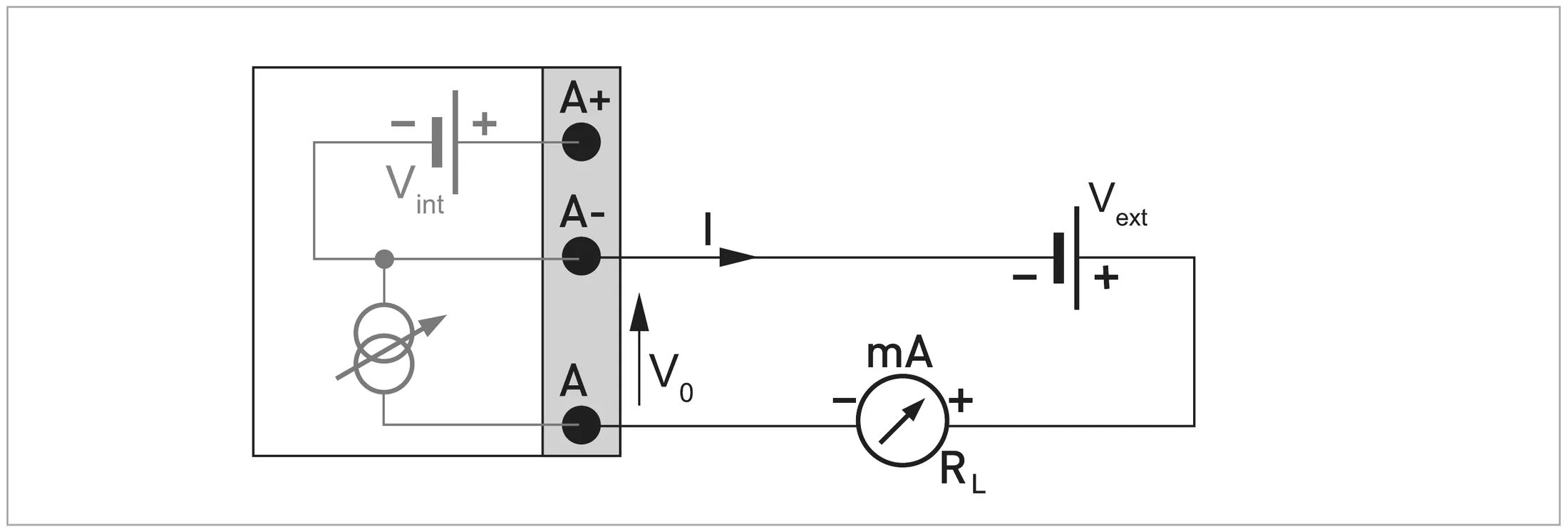
Current output passive Ip (Basic I/O): Vext ≤ 32 VDC, I ≤ 22 mA, V0 ≥ 1.8 V, RL ≤ (Vext - V0) / Imax
Ngõ ra dòng passive Ip (Basic I/O): Vext ≤ 32 VDC, I ≤ 22 mA, V0 ≥ 1.8 V, RL ≤ (Vext − V0) / ImaxCurrent output passive Ip (Basic I/O): Vext ≤ 32 VDC, I ≤ 22 mA, V0 ≥ 1.8 V, RL ≤ (Vext - V0) / Imax MA-C p.71
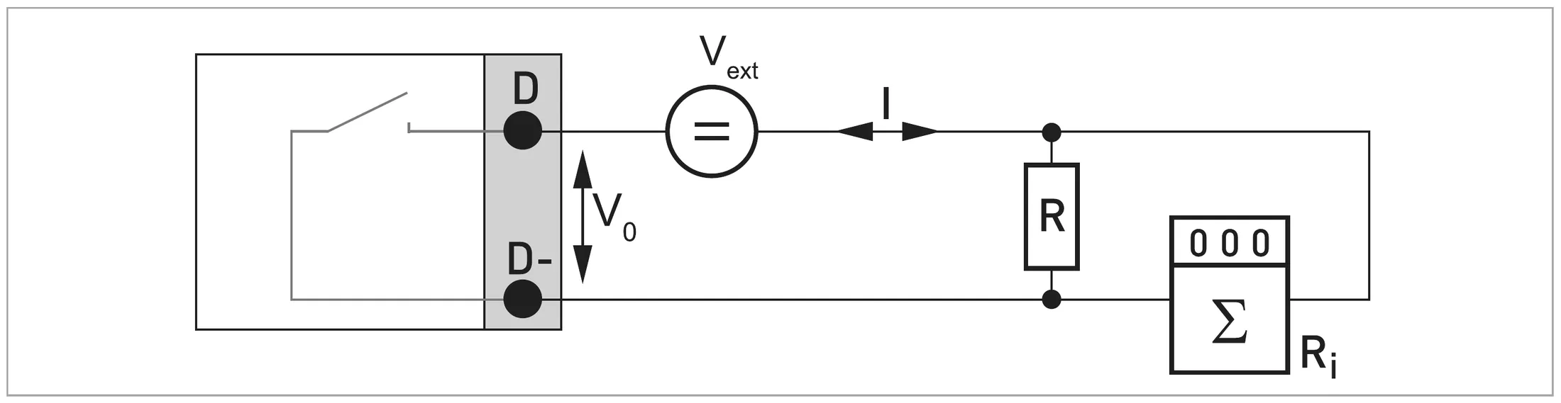
Pulse/frequency output passive Pp (Basic I/O, terminals D/D-): Vext ≤ 32 VDC; RL,min = (Vext - V0) / Imax
Ngõ ra xung/tần số passive Pp (Basic I/O, cực D/D−): Vext ≤ 32 VDC; RL,min = (Vext − V0) / ImaxPulse/frequency output passive Pp (Basic I/O, terminals D/D-): Vext ≤ 32 VDC; RL,min = (Vext - V0) / Imax MA-C p.72
Giới hạn điện I/O (Basic & Modular)I/O electrical limits (Basic & Modular) MA-C p.61–65, p.71–82
I/OI/OActiveActivePassivePassive
Ngõ ra dòng (HART)Current output (HART)Vint,nom = 24 VDC · I ≤ 22 mA · RL ≤ 1 kΩVext ≤ 32 VDC · I ≤ 22 mA · V0 ≥ 1.8 V · RL ≤ (Vext − V0) / Imax
Ngõ ra xung/tần sốPulse/frequency outputChỉ Modular: Vnom = 24 VDC · I ≤ 20 mAModular only: Vnom = 24 VDC · I ≤ 20 mAVext ≤ 32 VDC · fmax ≤ 100 Hz: I ≤ 100 mA · 100 Hz < fmax ≤ 10 kHz: I ≤ 20 mAVext ≤ 32 VDC · fmax ≤ 100 Hz: I ≤ 100 mA · 100 Hz < fmax ≤ 10 kHz: I ≤ 20 mA
RL max ngõ ra xungRL, max pulse output–f ≤ 100 Hz: 47 kΩ · f ≤ 1 kHz: 10 kΩ · f ≤ 10 kHz: 1 kΩ
Ngõ ra trạng thái / limit switchStatus output / limit switchChỉ Modular: Vint = 24 VDC · I ≤ 20 mA · RL ≤ 47 kΩModular only: Vint = 24 VDC · I ≤ 20 mA · RL ≤ 47 kΩVext ≤ 32 VDC · I ≤ 100 mA · RL,max = 47 kΩ
Ngõ vào điều khiểnControl inputChỉ Modular: Vint = 24 VDCModular only: Vint = 24 VDCBasic: 8 V ≤ Vext ≤ 32 VDC · Modular: 3 V ≤ Vext ≤ 32 VDCBasic: 8 V ≤ Vext ≤ 32 VDC · Modular: 3 V ≤ Vext ≤ 32 VDC
Ngõ vào dòng (Modular)Current input (Modular)Vint,nom = 24 VDC · I ≤ 22 mA · no HARTVext ≤ 32 VDC · I ≤ 22 mA · no HART

Ngõ ra trạng thái mở khi mất nguồn. NAMUR (PN/SN): mở 0.6 mA, đóng 3.8 mA.Status outputs are open when de-energised. NAMUR (PN/SN): open 0.6 mA, closed 3.8 mA.

  • Tần số > 100 Hz: phải dùng cáp có chống nhiễu nối bộ đếm.Above 100 Hz, shielded cables must be used to connect counters.
  • Cực không dùng không được nối với phần dẫn điện khác.Unused terminals must not have any conductive connection to other conductive parts.
  • HART: điện trở song song với HART communicator R ≥ 230 Ω.HART: parallel resistance to the HART communicator R ≥ 230 Ω.

MA-C p.69–72, p.88

Cực đấu theo đơn hàng DN2400 – Modbus + module A (dòng active) + module B (xung active)Terminals per DN2400 order – Modbus + module A (active current) + module B (active pulse) TD-C p.48Spec đơn hàng DN2400
CựcTerminalI/OI/ODùng choUsed for
A / A−Ia active4–20 mA về PLC/RTU – converter cấp nguồn vòng dòng (Modular: HART chỉ có ở cực C)4–20 mA to PLC/RTU – converter powers the loop (Modular: HART only on terminal C)
B / B−Pa / Sa activeNgõ ra xung về bộ đếm (spec: "active / high current")Pulse output to counter (spec: "active / high current")
C–Không dùngNot used
C−CommonModbus
DSign. B (D1)Modbus
D−Sign. A (D0)Modbus

Mã CG suy ra từ chuỗi đặt hàng converter "…GAC…": G = Modbus, điện trở đầu cuối không kích hoạt; A = module Ia active; C = module Pa/Sa active (TD-C p.48). Xác nhận theo nameplate và nhãn trong nắp ngăn đấu.CG inferred from the converter order string "…GAC…": G = Modbus, bus terminator not activated; A = Ia active module; C = Pa/Sa active module (TD-C p.48). Confirm on the nameplate and terminal-cover sticker.

Giới hạn điện I/O (Basic & Modular)I/O electrical limits (Basic & Modular) MA-C p.61–65, p.71–82
I/OI/OActiveActivePassivePassive
Ngõ ra dòng (HART)Current output (HART)Vint,nom = 24 VDC · I ≤ 22 mA · RL ≤ 1 kΩVext ≤ 32 VDC · I ≤ 22 mA · V0 ≥ 1.8 V · RL ≤ (Vext − V0) / Imax
Ngõ ra xung/tần sốPulse/frequency outputChỉ Modular: Vnom = 24 VDC · I ≤ 20 mAModular only: Vnom = 24 VDC · I ≤ 20 mAVext ≤ 32 VDC · fmax ≤ 100 Hz: I ≤ 100 mA · 100 Hz < fmax ≤ 10 kHz: I ≤ 20 mAVext ≤ 32 VDC · fmax ≤ 100 Hz: I ≤ 100 mA · 100 Hz < fmax ≤ 10 kHz: I ≤ 20 mA
RL max ngõ ra xungRL, max pulse output–f ≤ 100 Hz: 47 kΩ · f ≤ 1 kHz: 10 kΩ · f ≤ 10 kHz: 1 kΩ
Ngõ ra trạng thái / limit switchStatus output / limit switchChỉ Modular: Vint = 24 VDC · I ≤ 20 mA · RL ≤ 47 kΩModular only: Vint = 24 VDC · I ≤ 20 mA · RL ≤ 47 kΩVext ≤ 32 VDC · I ≤ 100 mA · RL,max = 47 kΩ
Ngõ vào điều khiểnControl inputChỉ Modular: Vint = 24 VDCModular only: Vint = 24 VDCBasic: 8 V ≤ Vext ≤ 32 VDC · Modular: 3 V ≤ Vext ≤ 32 VDCBasic: 8 V ≤ Vext ≤ 32 VDC · Modular: 3 V ≤ Vext ≤ 32 VDC
Ngõ vào dòng (Modular)Current input (Modular)Vint,nom = 24 VDC · I ≤ 22 mA · no HARTVext ≤ 32 VDC · I ≤ 22 mA · no HART

Ngõ ra trạng thái mở khi mất nguồn. NAMUR (PN/SN): mở 0.6 mA, đóng 3.8 mA.Status outputs are open when de-energised. NAMUR (PN/SN): open 0.6 mA, closed 3.8 mA.

Modbus – cực đấu (CG …G__ / H__)Modbus – terminals (CG …G__ / H__) TD-C p.48
CựcTerminalTín hiệuSignalGhi chúNote
A, BModule tùy chọn (tối đa 2)Optional modules (max. 2)Theo mã CG (ví dụ 4–20 mA) – kiểm tra nhãn trong nắpPer CG number (e.g. 4–20 mA) – check the sticker in the cover
C–Không dùngNot used
C−Common
DSign. B (D1)
D−Sign. A (D0)
Mã GCode GĐiện trở đầu cuối bus: không kích hoạtBus terminator: not activated
Mã HCode HĐiện trở đầu cuối bus: đã kích hoạtBus terminator: activatedDùng cho thiết bị ở cuối tuyến RS485For the device at the end of the RS485 line
Thông số Modbus của IFC 300IFC 300 Modbus data TD-C p.20
Thông sốParameterGiá trịValue
Giao thứcProtocolModbus RTU, Master / Slave, RS485
Dải địa chỉAddress range1…247
Function code hỗ trợSupported function codes03, 04, 16
Baud rate1200, 2400, 4800, 9600, 19200, 38400, 57600, 115200
INFORMATION
Chức năng và bảng thanh ghi Modbus mô tả trong tài liệu bổ sung Modbus của IFC 300 (supplementary instructions) – tài liệu này chưa có trong bộ hồ sơ hiện tại; liên hệ Lạc Việt để nhận bản phù hợp phiên bản thiết bị.Modbus functions and the register map are in the IFC 300 Modbus supplementary instructions – not in the current document set; contact Lạc Việt for the edition matching your device. MA-C p.100–101

Lạc ViệtĐi cáp RS485 xoắn đôi có chống nhiễu, đi riêng với cáp động lực; chỉ kích hoạt điện trở đầu cuối (mã H) ở thiết bị cuối tuyến; thống nhất địa chỉ, baud rate, parity với đơn vị SCADA trước khi lên hiện trường.Use shielded twisted-pair RS485 cable routed away from power cables; activate the terminator (code H) only on the last device; agree address, baud rate and parity with the SCADA team before site work.

MA-C p.90–93 Chi tiết trong HandbookDetails in the Handbook ↗
  • Thiết bị lắp đúng quy định địa phương.The device is mounted in compliance with local regulations.
  • Đấu nguồn đúng quy định cho thiết bị đo.Power connections comply with local regulations for measuring devices.
  • Các ngăn đấu dây đã siết, nắp đã vặn chặt.Terminal compartments tightened and covers screwed on.
  • Thông số điện của nguồn cấp đúng.Electrical data of the power supply are correct.

MA-C p.90

Hệ đo được giao sẵn sàng hoạt động, thông số đã cài tại nhà máy theo đơn hàng. Khi cấp nguồn, thiết bị tự kiểm tra rồi bắt đầu đo. Phím ↑ ↓ chuyển giữa 2 trang giá trị đo, trang đồ thị và trang trạng thái.The device is supplied ready for operation with factory settings per the order. On power-up a self test runs, then measurement starts. Keys ↑ and ↓ switch between the two measured value pages, the trend page and the status list. MA-C p.90

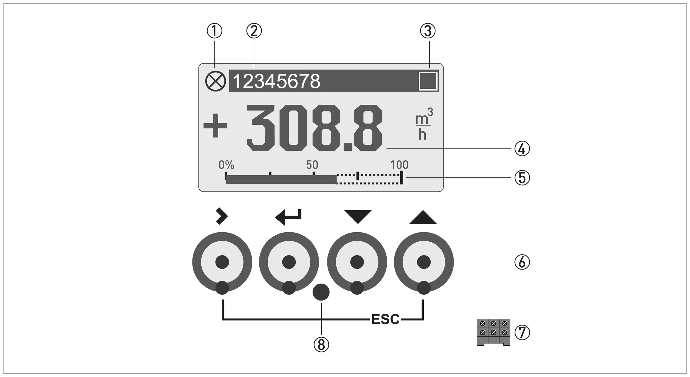
Display and operating elements (example: flow indication with 2 measuring values)
  1. 1Trạng thái thiết bịIndicates the device status
  2. 2Tag (chỉ hiện nếu đã nhập)Tag number (only if entered previously)
  3. 3Trạng thái phím và khóaIndicates the key and lock status
  4. 4Đại lượng đo thứ nhất, cỡ chữ lớnFirst measured variable in large representation
  5. 5BargraphBargraph indication
  6. 6Phím thao tác (quang và cơ): > ↲ ↓ ↑Operating keys, optical and mechanical: > ↲ ↓ ↑
  7. 7Cổng GDC bus (không có ở mọi phiên bản)Interface to the GDC bus (not present in all versions)
  8. 8Cảm biến hồng ngoại (không có ở mọi phiên bản)Infrared sensor (not present in all versions)
Màn hình và phím thao tác (ví dụ trang đo 2 giá trị)Display and operating elements (example: flow indication with 2 measuring values) MA-C p.91
INFORMATION
Sau 5 phút không thao tác, thiết bị tự về chế độ đo – dữ liệu đã sửa mà chưa lưu sẽ không được lưu.After 5 minutes of inactivity the device returns to measuring mode – changed data is not saved. MA-C p.91

Lạc ViệtTrước khi đọc số: mở van từ từ, xả hết khí, xác nhận ống đầy (không có thông báo empty pipe; độ dẫn B2.5 ổn định).Before reading values: open valves slowly, vent all air, confirm a full pipe (no empty pipe message; B2.5 conductivity stable).

Ảnh thực tế – theo cấu hình đang chọnIn the field – for the selected configuration

Màn hình & phím IFC 300 (①②③ theo TD)
Màn hình & phím IFC 300 (①②③ theo TD)IFC 300 display & keys (①②③ per TD) © KROHNE · làm nét bằng AI, không thêm bớt chi tiếtAI-sharpened, no details added TD-C p.3

MA-C p.97–121 Chi tiết trong HandbookDetails in the Handbook ↗
Vào menu: giữ phím > 2.5 s ở chế độ đo. ↑↓ chọn, > vào, ↲ lùi/nhận. Đường phím trong bảng tính từ chế độ đo (Basic I/O).Enter the menu: hold > for 2.5 s in measuring mode. ↑↓ select, > enter, ↲ back/accept. Key paths below start from measuring mode (Basic I/O). MA-C p.93

NIÊM PHONG / SEAL
Đồng hồ custody transfer có niêm chì: jumper khóa các thông số liên quan pháp định. Không phá niêm; mọi thay đổi thông số khóa phải có đơn vị kiểm định/KROHNE. Các mục không khóa (đơn vị hiển thị, Modbus…) kiểm tra trên thiết bị trước khi cài.Custody-transfer meter with lead seals: the jumper locks the legally relevant parameters. Do not break the seals; changes to locked parameters require the verification body/KROHNE. Check on the device which items (display units, Modbus…) remain editable. MA-C p.91Spec đơn hàng DN2400
NIÊM PHONG / SEAL
DN, GK/GKL, tần số kích từ, zero ảnh hưởng hiệu chuẩn: chỉ kiểm tra khớp nameplate, không sửa. Đồng hồ pháp định: các thông số này bị khóa.DN, GK/GKL, field frequency and zero affect calibration: only check against the nameplate, do not change. Custody-transfer meters: these parameters are locked. MA-C p.24, p.91

MA-C p.104, p.111–113 Chi tiết trong HandbookDetails in the Handbook ↗

  1. Ống đầy, đã xả khí; ghi giá trị thực ở menu B2: độ dẫn (B2.5), nhiễu điện cực (B2.6), profile dòng (B2.7), điện trở cuộn (B2.8).Pipe full and vented; record B2 actual values: conductivity (B2.5), electrode noise (B2.6), flow profile (B2.7), coil resistance (B2.8).
  2. Mô phỏng ngõ ra để kiểm tra SCADA/PLC: dòng C2.2.14, xung C2.5.13 (Basic I/O) – đối chiếu giá trị nhận được.Simulate outputs to test SCADA/PLC: current C2.2.14, pulse C2.5.13 (Basic I/O) – compare received values.
  3. So sánh lưu lượng hiển thị với lưu lượng bơm/đồng hồ tham chiếu (nếu có) và kiểm tra chiều dòng (C1.2.2).Compare displayed flow with pump/reference meter (if any) and check the flow direction (C1.2.2).
  4. Lưu cài đặt: C5.6.2 save settings → backup 1.Save settings: C5.6.2 save settings → backup 1.

MA-C p.103, p.106, p.111, p.113, p.119

Zero calibration C1.1.1: break / standard (cài đặt nhà máy) / manual (−1.00…+1 m/s) / automatic (lấy giá trị hiện tại làm zero mới).Zero calibration C1.1.1: break / standard (factory setting) / manual (-1.00...+1 m/s) / automatic (current value becomes the new zero). MA-C p.104

Lạc ViệtChỉ chạy zero "automatic" khi ống đầy và dòng chảy đã dừng hoàn toàn (đóng van hai phía); nếu không chắc, giữ "standard". Kiểm định/kiểm tra tại chỗ bằng OPTICHECK: liên hệ Lạc Việt.Run an "automatic" zero only with a full pipe and flow completely stopped (valves closed both sides); if unsure keep "standard". For on-site verification with OPTICHECK, contact Lạc Việt.

Ảnh thực tế – theo cấu hình đang chọnIn the field – for the selected configuration
Lắp DN1000 lên bệ kiểm định
Lắp DN1000 lên bệ kiểm địnhMounting the DN1000 on the verification rig Ảnh thực tế – Lạc Việt · DN1000 · kiểm định tại Trung tâm đo lường TP.HCM · 2025 · chỉnh sửa nhẹ (retouch), không thay đổi thiết bịReal photo – Lạc Việt · DN1000 · verification at the HCMC metrology centre · 2025 · lightly retouched, equipment unchanged
Kiểm định DN1000 trên bệ chuẩn
Kiểm định DN1000 trên bệ chuẩnVerifying the DN1000 on the reference rig Ảnh thực tế – Lạc Việt · DN1000 · kiểm định tại Trung tâm đo lường TP.HCM · 2025 · chỉnh sửa nhẹ (retouch), không thay đổi thiết bịReal photo – Lạc Việt · DN1000 · verification at the HCMC metrology centre · 2025 · lightly retouched, equipment unchanged

Ảnh thực tế – theo cấu hình đang chọnIn the field – for the selected configuration
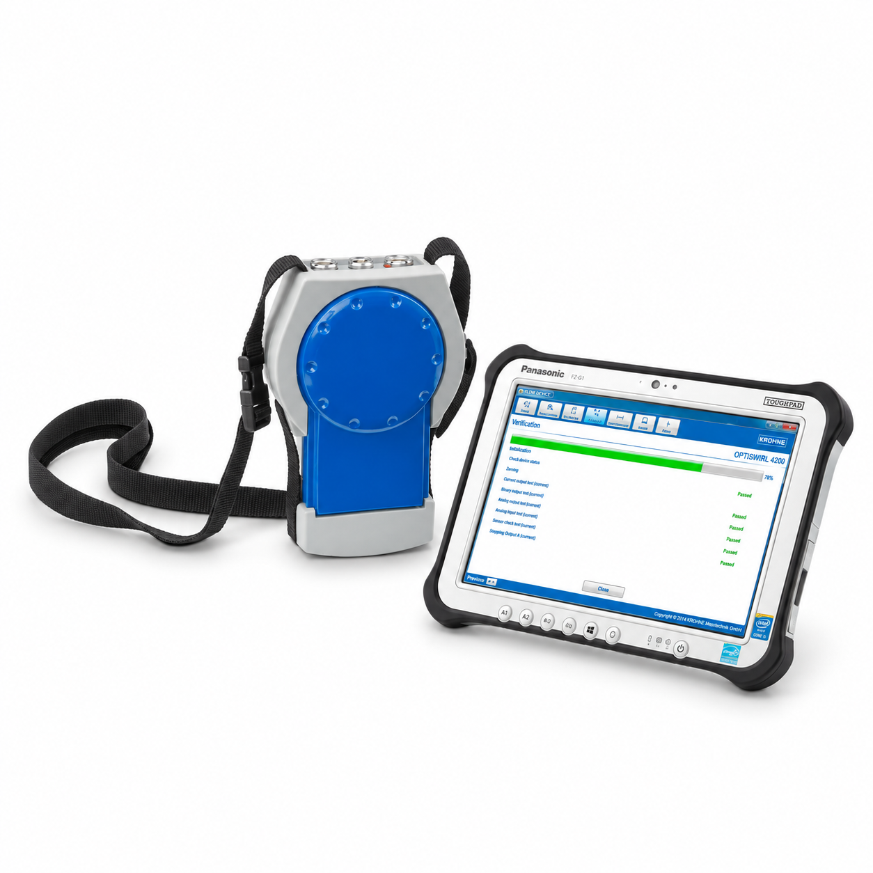
OPTICHECK Master – bộ kiểm tra tại hiện trường (verification box + tablet)
OPTICHECK Master – bộ kiểm tra tại hiện trường (verification box + tablet)OPTICHECK Master – on-site verification kit (verification box + tablet) © KROHNE · Màn hình tablet là ví dụ kiểm tra OPTISWIRL 4200 (vortex); OPTICHECK cũng kiểm tra được OPTIFLUX qua IFC 300 C/F/W/R (TD OPTICHECK tr. 7)Tablet screen shows an OPTISWIRL 4200 (vortex) check; OPTICHECK also verifies OPTIFLUX via IFC 300 C/F/W/R (TD OPTICHECK p.7) TD OPTICHECK R04 p.3, p.5, p.7

MA-S p.28–29MA-C p.123–131 Chi tiết trong HandbookDetails in the Handbook ↗
Thông báo trạng thái theo NAMUR NE 107 (F lỗi, C kiểm tra chức năng, S ngoài đặc tính, M cần bảo trì, I thông tin). Xem trang trạng thái bằng ↑↓; tra cứu thông báo và cách xử lý trong Handbook.Status messages follow NAMUR NE 107 (F failure, C function check, S out of specification, M maintenance required, I information). View the status page with ↑↓; look up messages and actions in the Handbook. MA-C p.123–129

  • Phụ tùng chức năng được duy trì 3 năm sau lô sản xuất cuối.Functionally adequate spare parts are kept for 3 years after the last production run.
  • Sửa chữa chỉ do nhà sản xuất hoặc đơn vị được ủy quyền thực hiện.Repairs must be carried out exclusively by the manufacturer or authorised companies.
  • Gửi trả thiết bị: súc rửa/trung hòa và kèm giấy xác nhận an toàn (mẫu đặt ngoài bao bì).Returns: rinse/neutralise and enclose the safe-handling certificate (form accessible from outside the packaging).

MA-S p.28–29MA-C p.130–131

Manual không quy định chu kỳ hay quy trình vệ sinh điện cực; IFC 300 có chẩn đoán nhiễu điện cực và profile dòng (C1.3.13, C1.3.10) để phát hiện bám cặn.The manual gives no electrode cleaning interval or procedure; the IFC 300 diagnoses electrode noise and flow profile (C1.3.13, C1.3.10) to detect fouling. MA-C p.107–108

Lạc ViệtMỗi lần kiểm tra: xem trang trạng thái, ghi B2.5–B2.7 và so với giá trị lúc bàn giao; nước thô nhiều cặn nên kiểm tra dày hơn mùa lũ. Kiểm tra mái che, gioăng nắp, nước đọng trong hố đo.Each visit: check the status page, log B2.5–B2.7 and compare with handover values; check more often in the flood season for silty raw water. Inspect the sun shade, cover gaskets and standing water in the pit.

Ảnh hiện trường – dự án Lạc Việt: DN1000 (kiểm định, 2025) · DN2400 (TP.HCM, 2017)Site photos – Lạc Việt projects: DN1000 (verification, 2025) · DN2400 (HCMC, 2017)

Lạc ViệtẢnh hiện trường do Lạc Việt cung cấp. Ảnh thật đã chỉnh sáng/làm nét; ảnh dựng hình được gắn nhãn "Ảnh minh họa".Site photos provided by Lạc Việt. Real photos have adjusted brightness/sharpness; the staged image is labelled "Illustration".
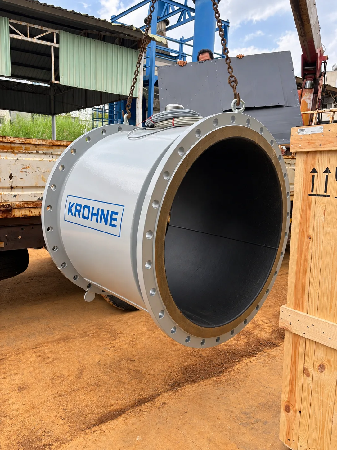
Tiếp nhận DN1000 tại trung tâm kiểm định
Tiếp nhận DN1000 tại trung tâm kiểm địnhDN1000 received at the verification centre Ảnh thực tế – Lạc Việt · DN1000 · kiểm định tại Trung tâm đo lường TP.HCM · 2025 · chỉnh sửa nhẹ (retouch), không thay đổi thiết bịReal photo – Lạc Việt · DN1000 · verification at the HCMC metrology centre · 2025 · lightly retouched, equipment unchanged
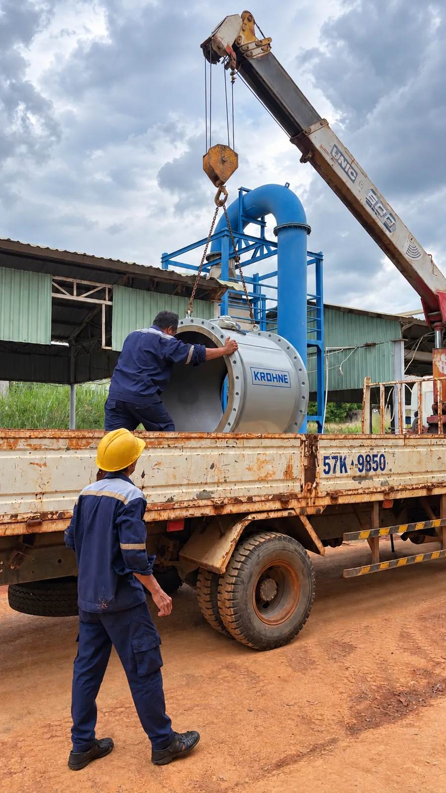
Bốc dỡ DN1000 từ xe cẩu
Bốc dỡ DN1000 từ xe cẩuUnloading the DN1000 from the crane truck Ảnh thực tế – Lạc Việt · DN1000 · kiểm định tại Trung tâm đo lường TP.HCM · 2025 · chỉnh sửa nhẹ (retouch), không thay đổi thiết bịReal photo – Lạc Việt · DN1000 · verification at the HCMC metrology centre · 2025 · lightly retouched, equipment unchanged
Cẩu nâng DN1000
Cẩu nâng DN1000Lifting the DN1000 Ảnh thực tế – Lạc Việt · DN1000 · kiểm định tại Trung tâm đo lường TP.HCM · 2025 · chỉnh sửa nhẹ (retouch), không thay đổi thiết bịReal photo – Lạc Việt · DN1000 · verification at the HCMC metrology centre · 2025 · lightly retouched, equipment unchanged
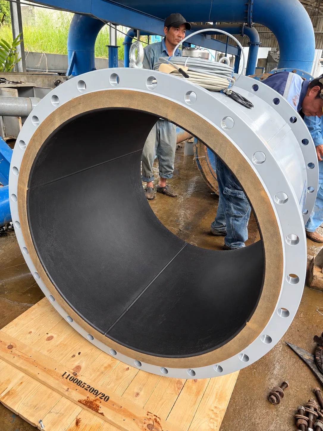
Lòng ống đo DN1000 (lớp lót)
Lòng ống đo DN1000 (lớp lót)DN1000 measuring tube bore (liner) Ảnh thực tế – Lạc Việt · DN1000 · kiểm định tại Trung tâm đo lường TP.HCM · 2025 · chỉnh sửa nhẹ (retouch), không thay đổi thiết bịReal photo – Lạc Việt · DN1000 · verification at the HCMC metrology centre · 2025 · lightly retouched, equipment unchanged
Lắp DN1000 lên bệ kiểm định
Lắp DN1000 lên bệ kiểm địnhMounting the DN1000 on the verification rig Ảnh thực tế – Lạc Việt · DN1000 · kiểm định tại Trung tâm đo lường TP.HCM · 2025 · chỉnh sửa nhẹ (retouch), không thay đổi thiết bịReal photo – Lạc Việt · DN1000 · verification at the HCMC metrology centre · 2025 · lightly retouched, equipment unchanged
Kiểm định DN1000 trên bệ chuẩn
Kiểm định DN1000 trên bệ chuẩnVerifying the DN1000 on the reference rig Ảnh thực tế – Lạc Việt · DN1000 · kiểm định tại Trung tâm đo lường TP.HCM · 2025 · chỉnh sửa nhẹ (retouch), không thay đổi thiết bịReal photo – Lạc Việt · DN1000 · verification at the HCMC metrology centre · 2025 · lightly retouched, equipment unchanged
Tiếp nhận đồng hồ DN2400 tại công trường
Tiếp nhận đồng hồ DN2400 tại công trườngReceiving the DN2400 meter on site Ảnh hiện trường thật – Lạc Việt, TP.HCM 2017 · đã chỉnh sáng/làm nétReal site photo – Lạc Việt, HCMC 2017 · brightness/sharpness adjusted
Cẩu hạ đồng hồ DN2400 (thi công ban đêm)
Cẩu hạ đồng hồ DN2400 (thi công ban đêm)Lifting the DN2400 meter (night work) Ảnh hiện trường thật – Lạc Việt, TP.HCM 2017 · đã chỉnh sáng/làm nétReal site photo – Lạc Việt, HCMC 2017 · brightness/sharpness adjusted
Siết bulông mặt bích
Siết bulông mặt bíchTightening the flange bolts Ảnh hiện trường thật – Lạc Việt, TP.HCM 2017 · đã chỉnh sáng/làm nétReal site photo – Lạc Việt, HCMC 2017 · brightness/sharpness adjusted
Kiểm tra sau lắp đặt
Kiểm tra sau lắp đặtPost-installation check Ảnh hiện trường thật – Lạc Việt, TP.HCM 2017 · đã chỉnh sáng/làm nétReal site photo – Lạc Việt, HCMC 2017 · brightness/sharpness adjusted
Toàn cảnh hố đo sau lắp đặt
Toàn cảnh hố đo sau lắp đặtMeter chamber overview after installation Ảnh hiện trường thật – Lạc Việt, TP.HCM 2017 · đã chỉnh sáng/làm nétReal site photo – Lạc Việt, HCMC 2017 · brightness/sharpness adjusted
Hộp đấu nối trên sensor
Hộp đấu nối trên sensorConnection box on the sensor Ảnh hiện trường thật – Lạc Việt, TP.HCM 2017 · đã chỉnh sáng/làm nétReal site photo – Lạc Việt, HCMC 2017 · brightness/sharpness adjusted
Ảnh minh họa: Cẩu hạ đồng hồ điện từ DN lớn vào buồng ngầmẢnh minh họaIllustration
Cẩu hạ đồng hồ điện từ DN lớn vào buồng ngầmLowering a large-DN electromagnetic flowmeter into an underground chamber Ảnh minh họa (dựng hình) – không phải ảnh công trìnhIllustration (staged image) – not a project photo

Ghi chú đối chiếu tài liệu gốcSource cross-check notes

Điểm tài liệu KROHNE mâu thuẫn hoặc thiếu dữ liệu cho DN lớn – cần xác nhận với KROHNE trước khi dùng chính thức.Points where the KROHNE documents conflict or lack large-DN data – confirm with KROHNE before official use.

Ký hiệu nguồn: MA-S = MA OPTIFLUX 2000 R09 · MA-C = MA IFC 300 R07 · TD-S = TD OPTIFLUX 2000 R14 · TD-C = TD IFC 300 R10. Hình minh họa trích từ PDF gốc KROHNE. Nội dung gắn nhãn Lạc Việt là kinh nghiệm hiện trường/gợi ý, không phải quy định của KROHNE.Source codes: MA-S = MA OPTIFLUX 2000 R09 · MA-C = MA IFC 300 R07 · TD-S = TD OPTIFLUX 2000 R14 · TD-C = TD IFC 300 R10. Figures are taken from the original KROHNE PDFs. Content labelled Lạc Việt is field experience/suggestion, not a KROHNE requirement.

DỰ ÁN